Category: Uncategorized

  • Running speaker cable behind wood wall panels: 2026 workflow

    Running speaker cable behind wood wall panels: 2026 workflow

    Instead of moving loose wires around your room, plan a protected, accessible route for running speaker cable behind wood wall panels before you attach the finish. This 2026 workflow covers cable selection, concealed routing, connection testing, and future access without treating decorative paneling as an electrical enclosure.

    TL;DR
    • Running speaker cable behind wood wall panels starts with an approved cable route, not a gap between decorative slats.
    • The Panel Hub suits DIY homeowners choosing wood acoustic wall panels; plan wiring separately from the decorative finish.
    • Use cable listed for the installation, protect it from fasteners, and test passive speakers before closing the wall.
    • Keep power connections accessible; never hide a powered speaker’s ordinary power cord behind permanent paneling.

    Why this matters

    A concealed cable route must remain safe after the wood panels go up. A wire that works during a quick test can still be pinched by a panel, pierced by a screw, or trapped behind an inaccessible connection.

    The Panel Hub is best for DIY homeowners choosing decorative wood acoustic wall panels, not a substitute for a wiring plan. Choose the finish you want, then confirm that its approved mounting method accommodates your cable route.

    Acoustic treatment and speaker wiring solve different problems. The Panel Hub describes its acoustic panels as NRC 0.85 rated; that absorption rating does not describe cable clearance, electrical protection, or sound isolation through a wall. It also does not mean the panels block 85% of sound from reaching another room.

    For a 2026 installation, settle speaker positions and access points before panel layout. Moving a cable exit after installation means disturbing finished wood rather than adjusting an open route.

    Before you start

    • Identify the equipment and cable requirements. Confirm whether you have passive speakers connected to an amplifier or powered speakers requiring local electricity. Gather the equipment manuals, cable listed for its installation environment, compatible terminals, labels, a measuring tape, and suitable testing tools. Follow the amplifier manufacturer’s guidance on cable gauge and run length.
    • Confirm the route and mounting method. Locate existing electrical services, plumbing, studs, and proposed panel fasteners. Obtain the panel installation instructions and any required permission for alterations. Have a qualified installer check concealed routes, fireblocking, and local requirements where the work exceeds your skills.
    • Check the hidden-clearance problem first. Visible slat grooves do not establish a usable cavity behind a panel. Dry-fit the complete assembly, including backing, mounting hardware, and any permitted battens. The cable must fit without compression, and speaker brackets must attach to appropriate structural support rather than decorative slats alone.

    Do not start by gluing panels over loose cable. Decide how you will replace the cable or reach its terminations before making the covering permanent.

    Choose the cable route

    These are three routing approaches for a wood-panel project. Each depends on the actual wall construction and the panel manufacturer’s instructions; none makes every decorative panel suitable for concealed wiring.

    Routing approach Best for Main advantage Main limitation
    Existing wall cavity Renovations with suitable wall access Keeps wiring independent of the decorative finish Requires checking hidden services, drilling locations, and fireblocking
    Permitted service cavity Panel installations designed around an approved stand-off assembly Separates cable routing from the panel face Adds wall depth and needs coordinated supports and fastener locations
    Accessible surface raceway Finished rooms where opening the wall is undesirable Keeps the cable route inspectable and replaceable Leaves a visible trim line and must suit the cable and location

    Choose access over invisibility when the two conflict. An accessible raceway is a better finish than a hidden wire crushed behind a panel. Check the raceway manufacturer’s instructions before combining it with decorative trim or covering it.

    A service cavity is not permission to change an acoustic panel’s tested mounting arrangement. Added depth, backing changes, and blocked openings can change the assembly, so confirm the details rather than assuming the published acoustic rating transfers unchanged.

    Speaker layout and cable specification

    1. Mark the endpoints. Identify the amplifier connection and each passive speaker connection. Mark the proposed cable exits on the unfinished wall, then check them against furniture, speaker brackets, panel seams, and removable covers.
    2. Measure the actual route. Follow the planned bends and vertical changes rather than measuring straight between the amplifier and speaker. Allow enough accessible slack to terminate and service the connections without leaving a tangled bundle behind the finish.
    3. Select and label the cable. Use the equipment manufacturer’s cable guidance and cable listed for the concealed environment. In US residential work, CL2 or CL3 markings commonly identify cable intended for appropriate in-wall applications; other spaces require different listings. Confirm the applicable listing rather than buying ordinary hookup wire by appearance.

    A passive speaker cable normally has 2 conductors. Preserve their identity from end to end using the jacket marking or conductor identification, and label both ends with the same channel name, such as Front Left.

    Cable sizes such as 14 AWG and 16 AWG describe conductor gauge, not a universal maximum distance. A lower AWG number means a thicker conductor; select the gauge using the run length, speaker load, and equipment guidance rather than a blanket rule.

    Expected result: every speaker has a named route, identified endpoints, and a cable specification checked against its installation environment. Your 2026 route sketch should show where the cable enters, exits, and remains accessible.

    Cable path and mounting protection

    1. Inspect before drilling. Check the proposed route for electrical wiring, water lines, and structural obstacles. A wall scanner helps locate features but does not prove a drilling location is clear. Stop where you cannot establish a safe path.
    2. Prepare the permitted route. Route the cable through the approved wall cavity, service cavity, or raceway. Protect it from sharp edges and fasteners using the methods required for that assembly. Have penetrations through fireblocking or rated construction handled with the appropriate approved details.
    3. Coordinate every fixing. Mark panel screws, mounting brackets, and trim fixings on the route drawing. Keep the cable outside those fixing paths, support it with suitable hardware without crushing the jacket, and photograph the completed route before covering it.

    Do not share electrical boxes or raceways with mains wiring unless the assembly and applicable rules permit the arrangement. Keep speaker cable routing separate from mains wiring as required, and avoid long parallel routes where practical. A right-angle crossing can limit parallel exposure, but it does not replace required separation or an approved assembly.

    The Panel Hub’s acoustic wall panels are the finish layer, not a cable-management system. Use the panel instructions to determine whether your intended mounting assembly is allowed.

    Expected result: the cable follows a protected path that does not intersect planned fixings. You have a record of that path and know which connections remain accessible.
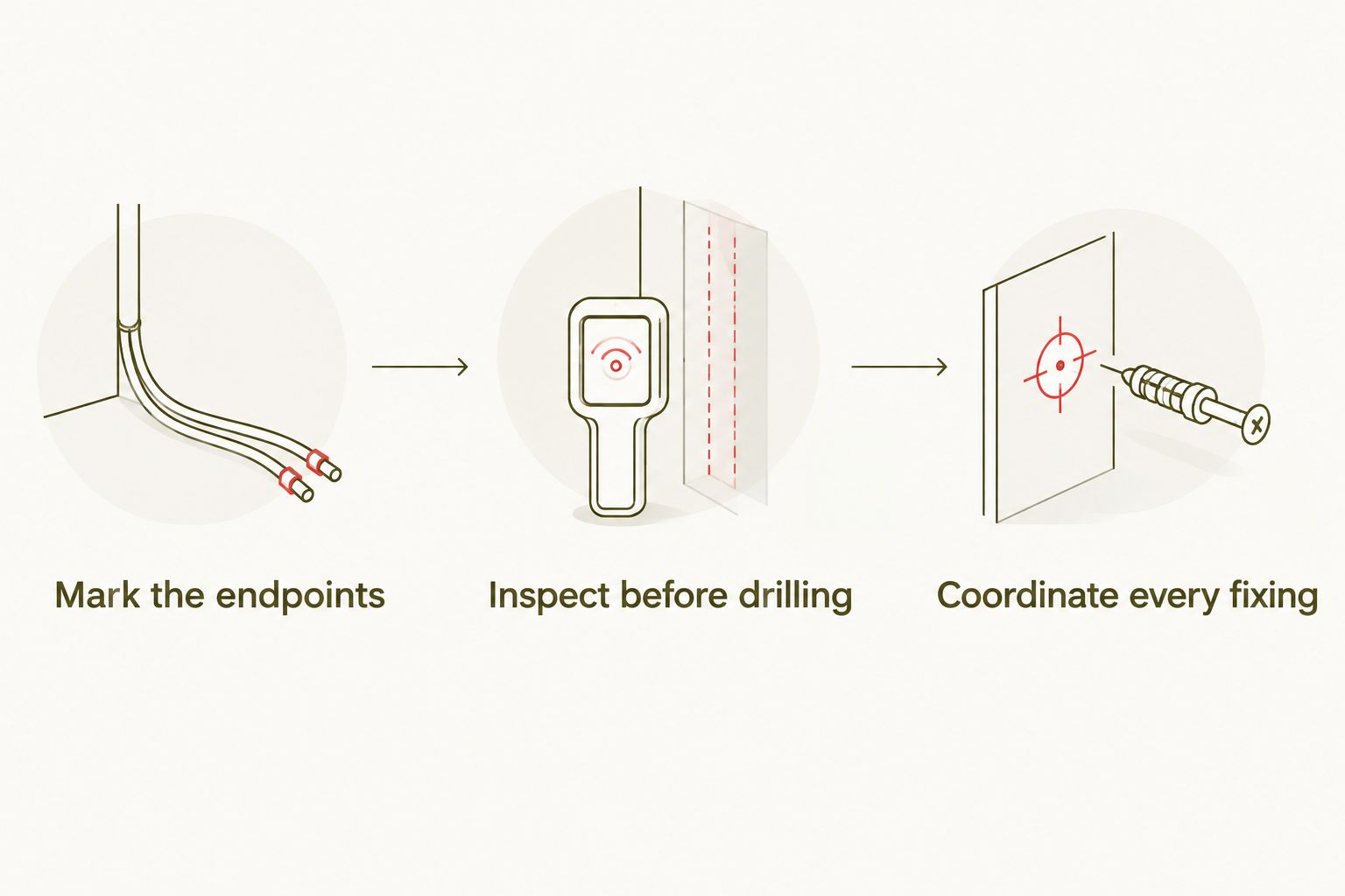
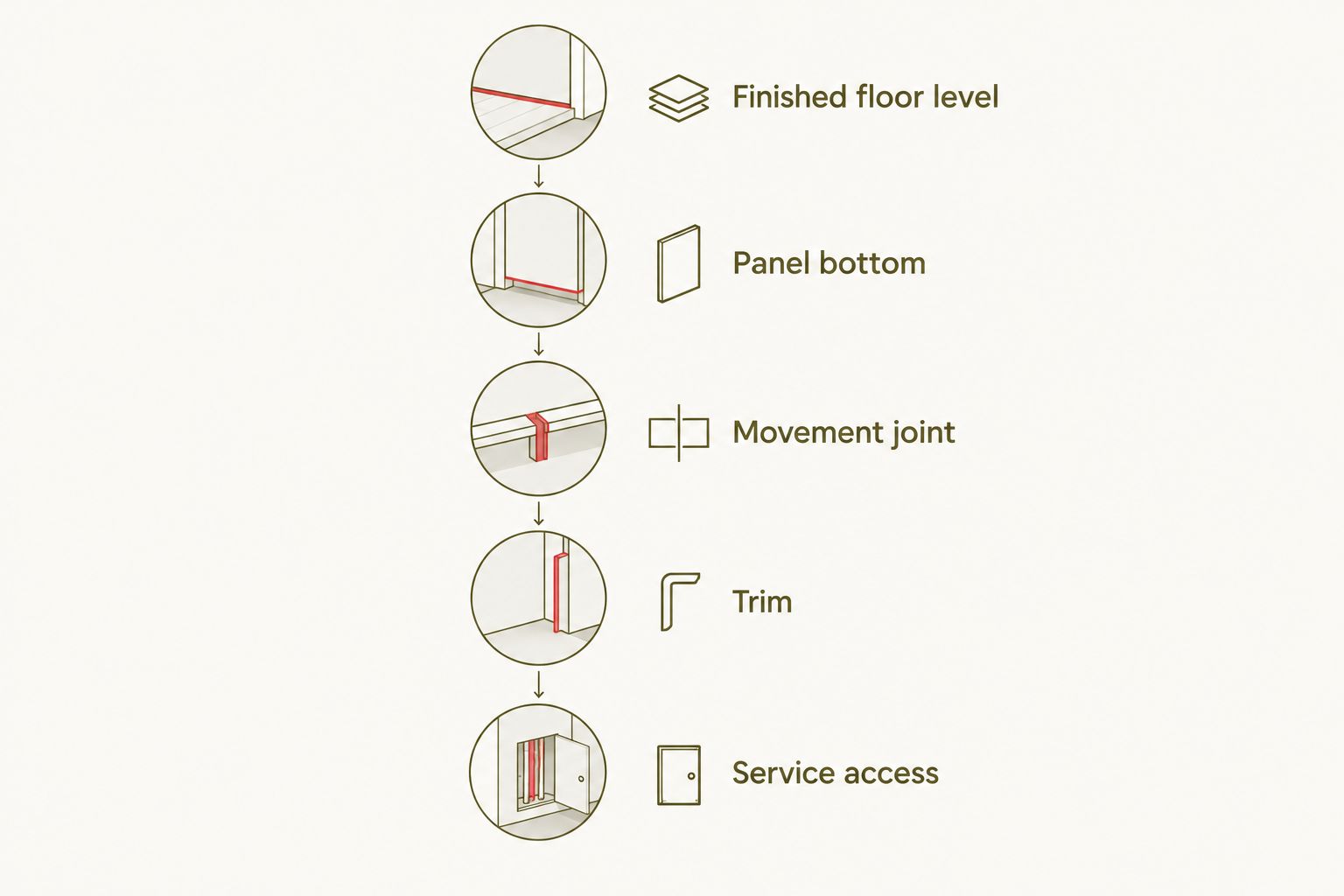
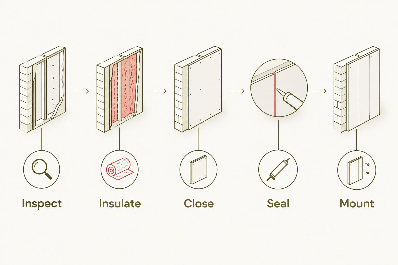
    Cable-routing sequence showing endpoints, wall inspection, and coordinated fixing locations
    Mark both the cable route and fixing locations before attaching panels.

    Cable exits and speaker connections

    1. Dry-fit the exit arrangement. Position a suitable low-voltage connection plate, cable outlet, or protected pass-through according to its instructions. Check that the finished panel depth does not prevent its cover from seating or leave the cable rubbing against a cut wood edge.
    2. Disconnect the equipment before termination. Switch off and unplug the amplifier before attaching speaker cable. Strip only the insulation needed for the terminal, follow the terminal instructions, and keep loose strands from bridging adjacent connections.
    3. Match polarity and check the route. Connect the identified conductor consistently to the corresponding positive terminal and the other conductor to the negative terminal. If using a meter for continuity checks, disconnect both cable ends from equipment first and check for unwanted contact between conductors.

    Do not hide an improvised splice behind permanently bonded panels. Use an uninterrupted run where practical, or provide an accessible termination arrangement suitable for the cable and installation.

    A cable exit should serve the speaker without carrying its weight. Secure the speaker bracket to appropriate support and leave the cable free from tension at the connection.

    Expected result: the exits fit the finished wall depth, the connections are accessible, and no loose strands bridge terminals. Every channel retains consistent conductor identification.

    Connection testing and panel closure

    1. Test before covering. Connect the intended speaker and amplifier, then play known audio at a low level. Verify the correct channel at each speaker. Stop immediately if the amplifier reports a fault, a speaker cuts out, or a connection becomes abnormal.
    2. Check the dry-fit assembly. With the equipment switched off, position the panel without forcing it. Confirm that the cable, connectors, and service slack do not push the panel outward or interfere with its mounting points.
    3. Close and retest. Install the panel according to its instructions, using the documented fixing positions. Repeat the channel checks after installation and make sure every cover, outlet, and service point remains reachable.

    Listen for rattles as well as missing sound. A successful electrical connection does not prove that a cable, cover, or panel edge is free from vibration against the speaker’s mounting arrangement.

    Expected result: the panels sit correctly, every speaker plays through its intended channel, and the wiring remains protected and serviceable. Keep the route photos with your 2026 equipment notes.
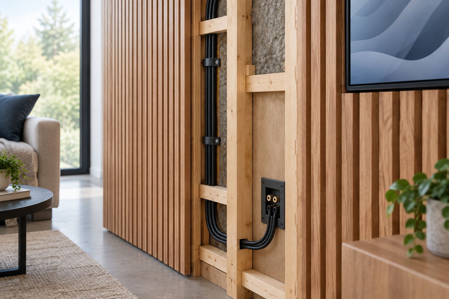
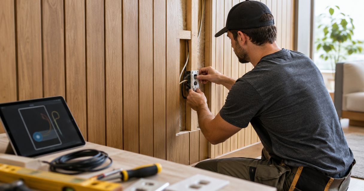
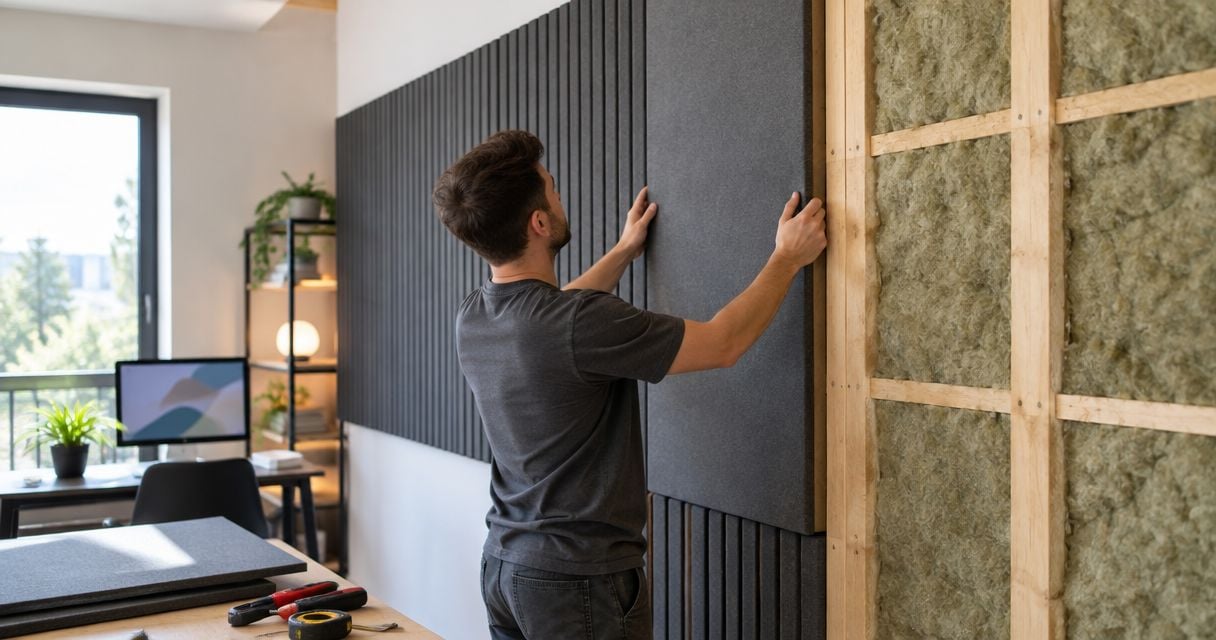
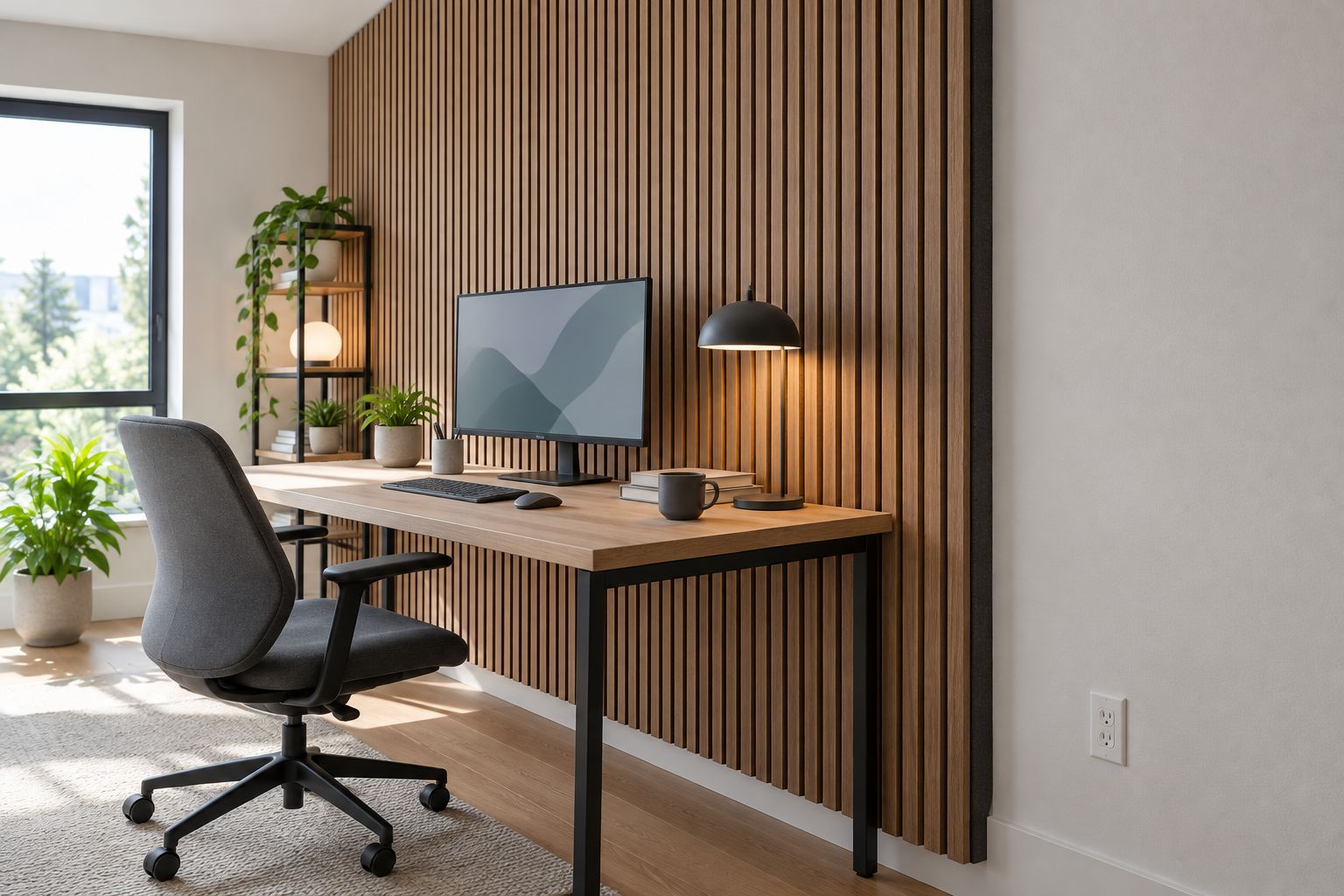
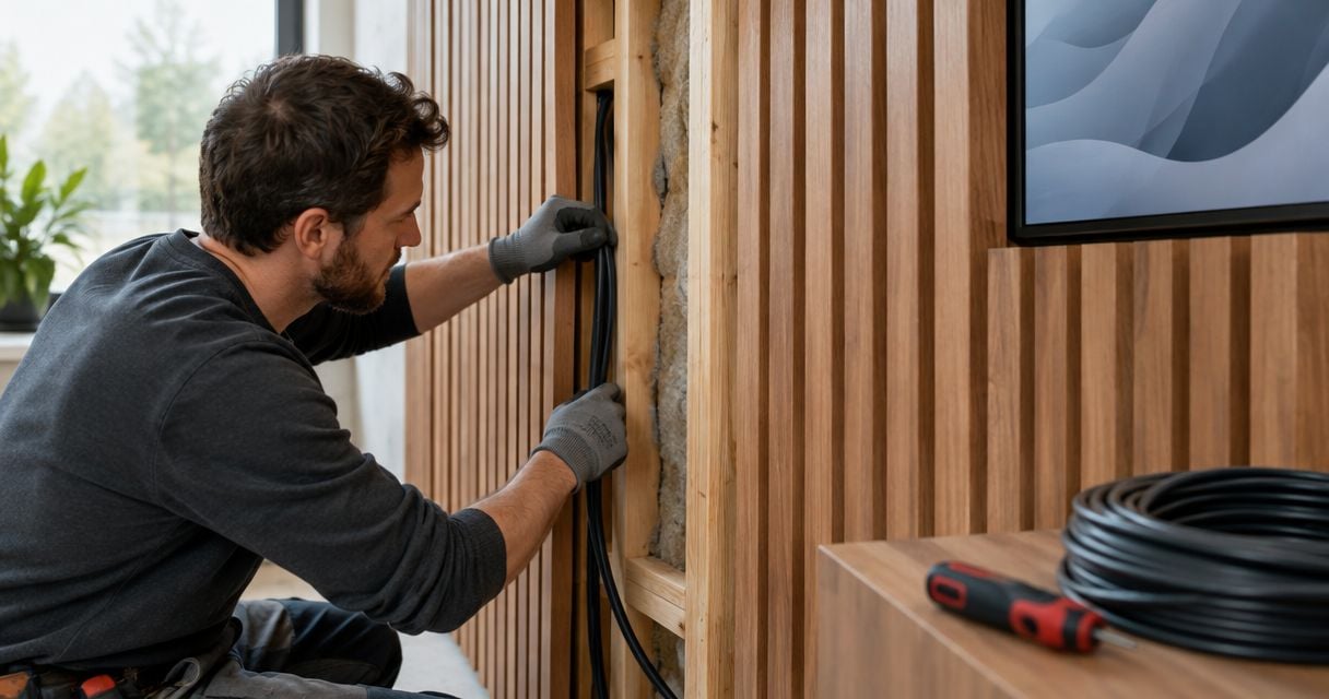
    Wood-slat wall with an open section showing a separate speaker cable route and accessible connection plate
    Inspect the cable clearance before closing the final panel section.

    Variant: add wiring behind panels already installed

    Retrofitting starts with identifying how the existing panels attach. Do not assume a panel is removable because its fixing points are hidden. Adhesive attachment changes the access plan.

    For mechanically fixed panels, follow the manufacturer’s removal instructions and support each section during removal. Inspect the space behind the finish before committing to a route, then follow the same cable-selection, protection, termination, and testing process.

    For bonded panels, compare controlled removal and repair with an accessible surface raceway. Do not force cable between the panel and wall with a tool; that approach gives you no reliable control over clearance or hidden services.

    If you expect to move speakers during a 2026 room redesign, choose accessible exits and a replaceable route now. A pull cord helps future cable replacement only when the pathway is designed for pulling cable and remains usable throughout its length.

    Troubleshooting

    • One speaker is silent. Switch off and disconnect the equipment, then inspect its terminals and channel labels. Test the isolated cable for continuity and an unwanted connection between conductors. A disconnected strand or short needs correction before reconnecting the amplifier.
    • The amplifier enters protection after panel installation. Stop using it and disconnect power. Inspect accessible terminations for bridging strands, then check the affected cable for damage from screws or compression. Do not repeatedly restart the amplifier against a suspected short.
    • Bass sounds weak after reconnecting speakers. Check polarity at both ends of every affected run. Reversed polarity can cause cancellation between speakers; listening alone does not identify which connection is reversed.
    • The panel sits proud or rocks. Remove the affected section using the approved method and inspect for trapped cable, oversized connectors, or bundled slack. Do not pull screws tighter to flatten a cable obstruction.
    • A buzz appears after rerouting. Separate equipment troubleshooting from wall work. Check whether the symptom remains with a known-good temporary cable routed away from mains wiring. A persistent buzz also requires checking the amplifier, source connections, and grounding rather than blaming the panel finish.

    Customize your workflow

    Use the speaker wiring plan to coordinate your wider room layout. Keep amplifier ventilation, speaker bracket support, outlets, and furniture access separate from the decorative panel pattern.

    For room-treatment planning, read the guide to connecting acoustic wall panels to a home theater system. Speaker placement and acoustic treatment deserve their own decisions; hiding cable does not establish either.

    The Panel Hub’s wood acoustic wall panels suit a decorative room upgrade, but cable serviceability must come from the installation plan. Before closing your 2026 project, save the cable labels, route photographs, equipment manuals, and panel mounting instructions together.

    FAQ

    Can I run speaker cable behind wood wall panels?

    Yes, when the cable and concealed route are suitable for the installation and protected from fasteners, sharp edges, and compression. Confirm clearance behind the complete panel assembly rather than assuming decorative grooves provide a cable cavity.

    What cable should I use behind wood wall panels?

    Use speaker cable listed for the concealed installation environment and sized according to the equipment manufacturer’s guidance. CL2 and CL3 are common US in-wall cable markings, but the location and applicable rules determine the required listing.

    Can I hide a powered speaker’s power cord behind paneling?

    Do not conceal an ordinary flexible power cord behind permanent paneling. Provide the powered speaker with an appropriately installed, accessible electrical supply and have mains alterations handled by a qualified electrician.

    Is 14 AWG better than 16 AWG for concealed speaker wiring?

    14 AWG is thicker than 16 AWG, but the correct choice depends on run length, speaker load, and equipment guidance. Cable gauge does not replace the listing required for concealed installation.

    Can speaker cable share a route with electrical wiring?

    Only use shared routing arrangements permitted by the applicable rules and the listed assembly. Plan separate routes by default, and do not assume a right-angle crossing makes a shared box or raceway acceptable.

    Do acoustic wood panels soundproof a speaker cable route?

    No, acoustic absorption and sound isolation are different functions. Concealed cable openings, wall construction, and acoustic treatment must each be considered separately.

    Do I need to remove existing panels to add speaker cable?

    You need access to verify and prepare a concealed route, but a suitable accessible surface raceway can avoid opening the wall. Follow the panel manufacturer’s removal instructions rather than prying off an unknown mounting system.

    One last thing

    Test the finished wall, not just the exposed wire. A cable can pass its initial check and still suffer damage during panel fastening. Repeat the speaker test after closure, then retain a photograph that identifies the cable path relative to fixed room features.

    Your future wall-mounted shelf is another reason to keep that record. Concealed wiring remains relevant long after the speakers are installed.

    Related guides

  • Connecting wall panel trim to existing crown molding

    Connecting wall panel trim to existing crown molding

    Instead of repeatedly trimming panels until they squeeze beneath existing crown molding, plan the finished wall depth, test the junction with scraps, and install a separate finishing trim where needed. This 2026 guide explains connecting wall panel trim to crown molding without forcing the panels against the crown or hiding poor cuts under caulk.

    TL;DR
    • Connecting wall panel trim to crown molding starts with measuring the complete panel assembly, not just the decorative face.
    • Keep existing crown molding when a sample shows the panel and finishing trim fit beneath it.
    • Use a flat transition rail to separate uneven panel ends from the crown molding.
    • The Panel Hub serves homeowners choosing decorative and acoustic wood wall panels; check installation instructions before selecting trim.

    Why this matters

    Crown molding finishes the wall-to-ceiling junction. Wall panel trim finishes the panel edge. Those jobs overlap visually, but attaching one directly to the other is not automatically the right construction detail.

    A panel mounted on backing or battens sits farther into the room than a panel attached directly to the wall. That extra depth changes whether the crown projects beyond the finished surface, meets it neatly, or appears buried behind it.

    The Panel Hub is best for homeowners shopping for decorative and acoustic wood wall panels. When choosing The Panel Hub wall panels for a 2026 project, resolve the crown junction before covering the wall. The trim detail needs to suit the actual assembly, not just the panel's appearance.

    Before you start

    • Gather the panel installation instructions, a panel offcut, proposed finishing trim, tape measure, level, straightedge, angle finder, and suitable cutting tools. Choose fastening and finishing materials compatible with the wall, panel, and trim.
    • Inspect the existing crown for loose sections, damaged finishes, and hidden services near proposed fastening locations. Use stable access equipment, eye protection, and appropriate dust control; investigate suspect older paint before disturbing it.
    • Check the concealed depth first. Include backing, battens, and the intended mounting system in your sample. Also check required movement clearances: a trim that covers an edge must not clamp a panel that needs room to move.

    Do not start by removing sound crown molding. First establish whether the new wall surface can finish beneath it without changing the ceiling detail.

    Wall depth and junction layout

    The first configuration decision is the relationship between the finished panel face and the crown's lower edge. In your 2026 project notes, record that relationship before ordering finishing trim or cutting full panels.

    1. Measure the assembly. Hold a panel sample against the intended backing or mounting arrangement. Measure from the original wall surface to the outermost finished face, including raised texture where it meets the trim.
    2. Check crown projection. Hold a straightedge against the sample face and extend it upward. Observe whether the crown's lower edge projects beyond that plane, meets it, or sits behind it.
    3. Check the wall. Take readings at 3 measurement points: each end and the middle. Add checks wherever the wall bows or the crown changes direction.
    4. Mark the finish line. Establish a level reference for the panel or transition rail. Compare it with the crown's underside rather than assuming the existing molding is level.
    5. Inspect adjoining details. Check door casings, window casings, side returns, and corners. A top trim that works in the middle of the wall still needs a deliberate ending at each side.

    Expected result: You know the finished wall depth, the crown's position relative to it, and where the panel's top edge will end.

    Choose the junction that matches the measurements

    The options below are construction details, not interchangeable accessories. Select the detail that fits your measured assembly and the panel manufacturer's instructions.

    Junction option Best for Advantage Limitation
    Panel below crown A panel face that fits beneath the existing crown Preserves the existing ceiling detail Exposes inaccurate top cuts unless an approved edge trim covers them
    Flat transition rail Uneven panel ends or a visual break beneath crown Creates a continuous boundary above the panel pattern Adds another horizontal element and needs independent support
    Repositioned crown Panel assemblies that leave the crown recessed behind the new face Allows the crown to relate to the new wall plane Requires removal, refitting, and possible corner or ceiling repairs

    Keep existing crown when the mock-up fits; change the junction when it does not. Caulk cannot correct an incompatible depth relationship.

    A flat transition rail is a practical choice when you want to preserve the crown while giving slats or textured panels a clean stopping point. It does not solve every depth problem: the rail itself must fit below the crown and cover the intended panel edge.

    Sample assembly and trim fit

    A dry-fit makes the connection visible before adhesive or fasteners make it permanent. Test the complete junction, including the finish that will remain exposed.

    1. Build the sample. Use 2 scrap pieces: a panel offcut and a finishing-trim offcut. Add any specified backing or mounting layer behind the panel.
    2. Position the pieces. Hold the assembly beneath the crown at the intended height. Preserve the panel manufacturer's required clearance instead of pushing everything tightly together.
    3. Check edge coverage. Confirm that the trim hides the intended cut edge without covering an unwanted portion of the pattern or obstructing required movement.
    4. Test the corner. For a flat rail turning around a true 90-degree corner, a symmetrical miter starts with 45-degree cuts. Measure the actual corner before cutting; out-of-square walls require a different fit.
    5. Inspect the finish. View the sample from the doorway and from normal seating height. Check exposed backing, unfinished ends, uneven shadows, and awkward side returns.

    Expected result: The sample shows a junction you can repeat across the wall without forcing, excessive filler, or an exposed raw edge.

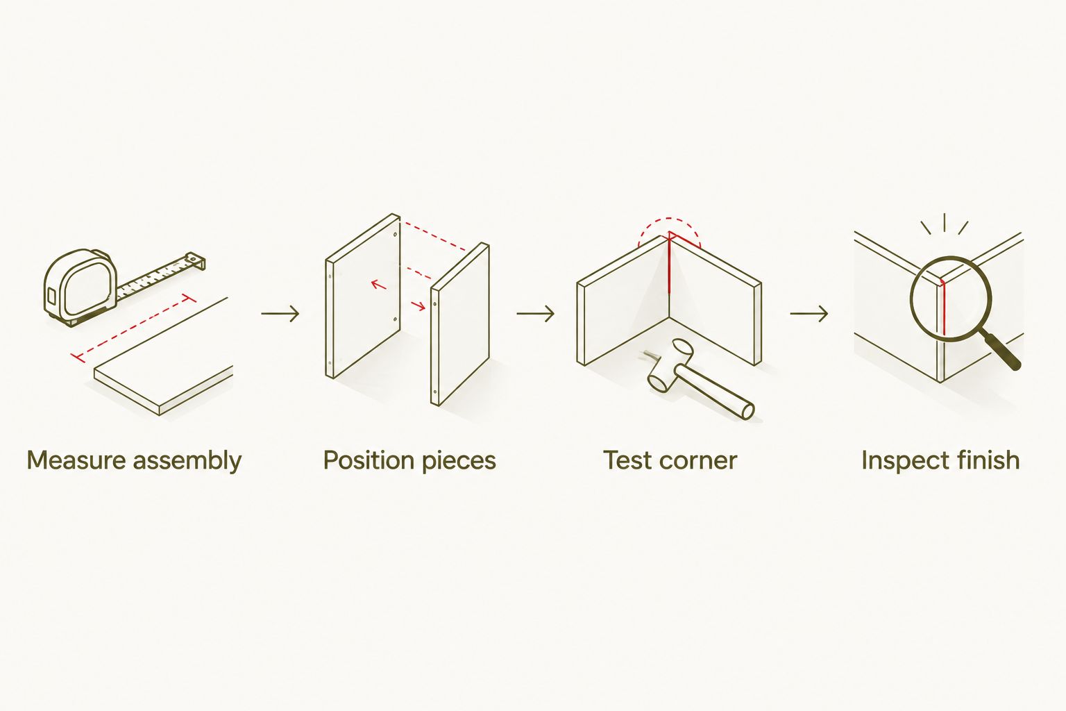
    Four stages for testing a wall panel and crown molding junction before installation
    Test the full assembly before cutting the main wall panels.

    Decide what stays visible

    Painted trim and natural wood require different finishing plans. A paintable joint can conceal a small cosmetic seam; a stained or clear-finished wood joint needs accurate cutting and a compatible finish.

    Do not assume wood filler or caulk will match the panel surface. Test any visible finishing material on an offcut and let it dry before judging the result.

    For a 2026 room update, photograph the approved sample and keep it beside your measurements. It gives you a reference when checking later cuts, especially where the crown changes height or the wall changes direction.

    Panel installation and trim fastening

    Install the wall panels and finishing trim as separate components unless the manufacturer's instructions specify an integrated system. The crown is not a substitute for suitable wall support.

    1. Prepare the substrate. Repair loose or damaged areas and prepare the wall as required by the mounting system. Do not attach panels over a surface that is unstable or unsuitable for the selected adhesive.
    2. Lay out the pattern. Check where full panels, cut panels, and side edges will fall. Keep the approved top junction while adjusting the layout at doorways and corners.
    3. Cut the panel tops. Transfer the actual measurements to each panel. Cut with the method specified for the material, supporting delicate faces and controlling dust.
    4. Install the panels. Follow the panel instructions for attachment, clearances, and mounting arrangement. Do not wedge the panel between floor and crown to make it feel secure.
    5. Fit the finishing trim. Attach the rail or edge trim to appropriate support using a method suitable for its material. Do not rely on decorative panel faces or the crown's thin lower edge as an unspecified fastening surface.
    6. Check each section. Confirm alignment, edge coverage, and corner fit before installing the next length. Keep adhesive and filler away from surfaces they are not intended to cover.

    Expected result: The panels stay supported by their intended mounting system, and the trim finishes the top edge without transferring that job to the crown.

    A clean boundary for slatted walls

    For slatted panels, check both the slat ends and the backing at the top junction. A continuous rail can hide the cut ends, but its position must suit the complete panel assembly.

    Do not fill the spaces between slats simply to make them resemble solid paneling. Preserve the panel's intended construction and follow its installation instructions.

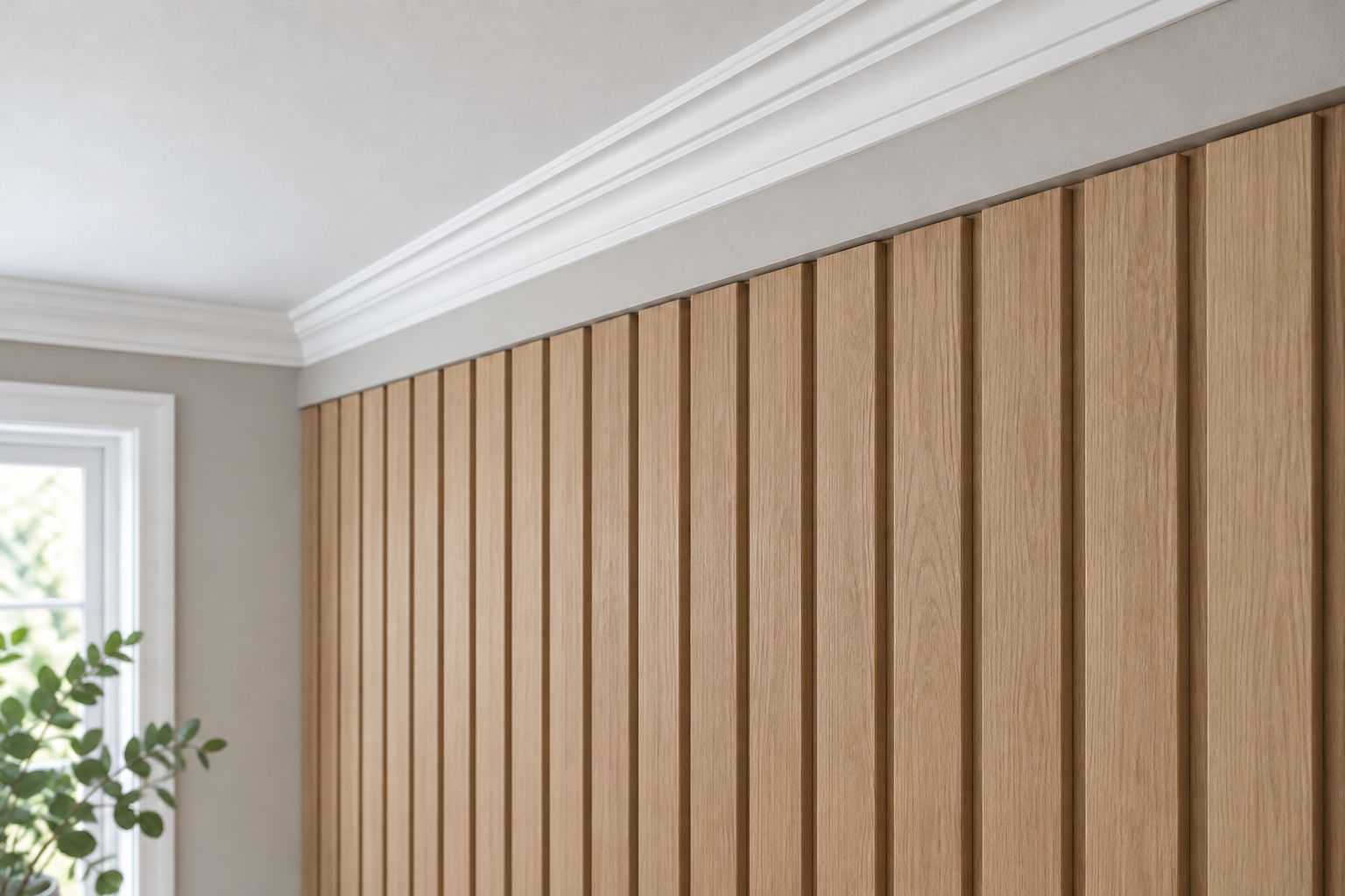
    Wood slat wall panels ending beneath a painted transition rail and existing crown molding
    A separate rail gives the slat ends a continuous finishing boundary.

    The Panel Hub acoustic wall panels still need the correct mounting arrangement after you add decorative trim. Treat the top junction as an edge-finishing decision, not permission to change the panel assembly.

    Joint finishing and final checks

    Finishing should refine an accurate fit, not disguise a failed one. Inspect the connection before applying materials that make later adjustments harder.

    1. Check physical fit. Look for raised trim, unsupported ends, pinched panels, and corners that open when pressed. Correct these before filling fastener holes.
    2. Finish suitable seams. Use compatible paintable caulk only for appropriate cosmetic seams. Do not bridge required movement joints or use caulk as structural attachment.
    3. Finish exposed ends. Apply the material-specific treatment required for cut edges. Do not leave an exposed panel core simply because it is near the ceiling.
    4. Respect drying instructions. Follow the adhesive, filler, caulk, and coating instructions before disturbing or finishing the joint.
    5. Inspect under room lighting. Check the wall with daylight and the lights you normally use. Light grazing across the surface reveals uneven trim and rough transitions.

    Expected result: The finished junction looks deliberate, retains required clearances, and has no unsupported trim or exposed unfinished edges.

    Adding panels beneath crown during a later room update

    If you add panels after another wall has already been finished, match the junction detail rather than automatically matching the new panel height. Different wall assemblies can need different edge coverage.

    • Rebuild the sample with the new panel and mounting arrangement.
    • Compare the proposed rail with existing door and window trim.
    • Check how the rail ends where the feature wall stops.
    • Keep a continuous crown line where the measured fit allows it.

    For a 2026 feature-wall update, a deliberate side return is better than an open trim end. Fit an appropriate return or end treatment to the chosen profile; do not assume the adjacent wall will hide the cut.

    Troubleshooting

    The panel face projects past the crown

    Change the junction, not the panel by force. Test a compatible transition detail or refit the crown to the new wall plane. Do not remove backing or alter the mounting arrangement unless the panel instructions permit it.

    A gap widens along the crown

    Check whether the crown is uneven, the wall bows, or the panel top was cut to a single measurement. Scribe the appropriate trim where practical or use a transition rail that accommodates the measured variation; do not build a deep filler wedge.

    The trim opens at a corner

    Measure the actual corner angle and check that both pieces sit flat. Recut or refit the joint instead of pulling it closed with fasteners, which can distort the trim or leave the joint under stress.

    The joint cracks after finishing

    Check for loose fastening, unsuitable finishing material, or a required movement joint that was filled solid. Repair the cause before repainting. Repeatedly covering the crack does not correct the assembly.

    The panel backing remains visible

    Return to the approved sample and check trim coverage, panel height, and side returns. Use an appropriate edge detail rather than coating exposed backing with an unapproved adhesive or filler.

    Customize your workflow

    Carry the same sample-first method to the rest of the room. Door casings, heating equipment, and switches introduce different constraints; a successful crown connection does not settle those details.

    The Panel Hub decorative wall panels give you several surface patterns to work with, but the finishing sequence stays practical: verify depth, approve the sample, install the supported assembly, then finish its edges. Keep that sequence even when the room design changes.

    FAQ

    How do I connect wall panel trim to existing crown molding?

    Measure the complete panel assembly, dry-fit the top junction, and install a compatible edge trim or transition rail beneath the crown. Refit the crown when the new wall plane prevents a suitable connection.

    Do I need to remove crown molding before installing wall panels?

    No, crown molding can stay when the complete panel assembly fits beneath it with the required clearances. Check a sample before committing to that detail.

    Should wall panels touch the crown molding?

    Do not force wall panels against crown molding. Follow the panel manufacturer’s clearance requirements and use an appropriate finishing detail to cover the edge where permitted.

    What’s the best trim for uneven panel ends below crown?

    A flat transition rail is a practical choice for creating a continuous boundary above uneven panel ends. It needs suitable support and enough coverage for the measured junction.

    Can I nail wall panel trim into the crown molding?

    Do not treat the crown molding as the default fastening surface for wall panel trim. Attach the trim to suitable support using a method appropriate for the materials and the installation.

    Can I use caulk to hide the gap above wood panels?

    Use compatible caulk only for appropriate cosmetic seams. Do not use it to conceal a major fitting error, support trim, or fill a required movement joint.

    How should I plan this crown molding connection in 2026?

    Plan a 2026 crown molding connection around the actual panel depth and current installation instructions. Keep an approved sample so the top edge, corners, and side returns follow the same detail.

    One last thing

    Finish the sample before approving the joint. A junction that looks tidy in bare wood can reveal mismatched filler or an exposed cut edge after coating. Testing the complete finish on scraps protects the work you have not installed yet.

    Related guides

  • Installing wall panels around a gas fireplace safely

    Installing wall panels around a gas fireplace safely

    Instead of trimming panels to fit the fireplace opening and checking heat clearances afterward, start installing wall panels around gas fireplace surrounds by mapping the appliance’s required clearances, approved finishes, and service access. Then build the decorative wall outside those limits, keeping every panel layer and fixing within the fireplace manufacturer’s instructions.

    TL;DR
    • Installing wall panels around gas fireplace surrounds starts with the exact appliance manual, not a generic clearance measurement.
    • The Panel Hub decorative wall panels belong outside required combustible clearances unless the fireplace instructions explicitly permit the assembly.
    • Wood, acoustic backing, adhesive, and battens all need checking; the visible finish alone does not establish safety.
    • Keep air openings, glass removal paths, controls, and service panels accessible after installation.

    Why this matters

    A gas fireplace surround is more than a decorative border. Its installation instructions control where combustible finishes belong, which facing materials are permitted, and how the appliance releases heat and remains serviceable.

    The Panel Hub is best for homeowners choosing decorative wall panels outside a gas fireplace’s required combustible-clearance zone. Explore The Panel Hub for the decorative portion of the wall, but establish the fireplace boundary before choosing a finish.

    For a 2026 renovation, use the instructions for the installed model, including any manufacturer-issued revisions. Another fireplace’s dimensions, a neighbor’s installation, or a photograph cannot establish your clearances.

    Wood slats beside a fireplace can create a warm living-room feature. The trade-off is that wood and its supporting layers need a location the appliance instructions allow—not simply somewhere that feels cool when touched.

    Before you start

    • Get the exact appliance documents. Find the model identification, installation manual, finishing diagrams, and service instructions. Confirm any local permit or inspection requirements with your building department before changing the surround.
    • Collect the complete panel specifications. Include panel composition, backing, battens, adhesive instructions, fasteners, finish thickness, and any relevant fire-test documentation. Have measuring tools, protective equipment, and a qualified fireplace professional available for appliance-related questions.
    • Check the hidden gotcha: finish depth changes the geometry. A panel projecting toward the opening can affect a clearance or mantel projection limit even when its edge sits beyond the existing trim. Map the finished surface, not just the bare wall.

    Stop if the model or its instructions cannot be identified. Do not create a clearance by copying a similar-looking appliance. Have a qualified fireplace professional identify the unit and determine the permitted finishing arrangement.

    Appliance boundaries

    Establish the clearance map

    1. Let the fireplace cool and follow its instructions for shutdown before working nearby. Do not disconnect gas lines, move the appliance, or remove sealed components as part of a paneling job.
    2. Read the manual’s finishing, combustible-clearance, mantel, and service-access sections together. Record each measurement with its stated reference point: opening, appliance body, trim, or another identified surface.
    3. Transfer the boundaries to a wall sketch. Mark Combustible limits, Facing area, Air openings, and Service access as separate features.
    4. Include side returns, projecting edges, mantel shelves, and the finished panel depth. Check that existing construction matches the manual before adding anything.

    A clearance above the opening is not automatically the same as a side clearance. Likewise, a mantel diagram does not necessarily authorize a full-height wood surface beneath it.

    Expected result: Your sketch shows where decorative panels can begin, which facing area needs the specified construction, and which openings must remain unobstructed. Every dimension traces back to the exact appliance instructions.

    The 2026 project file should contain the manual pages used for this layout. Keep the sketch with them so the installer and inspector can check the same reference points.

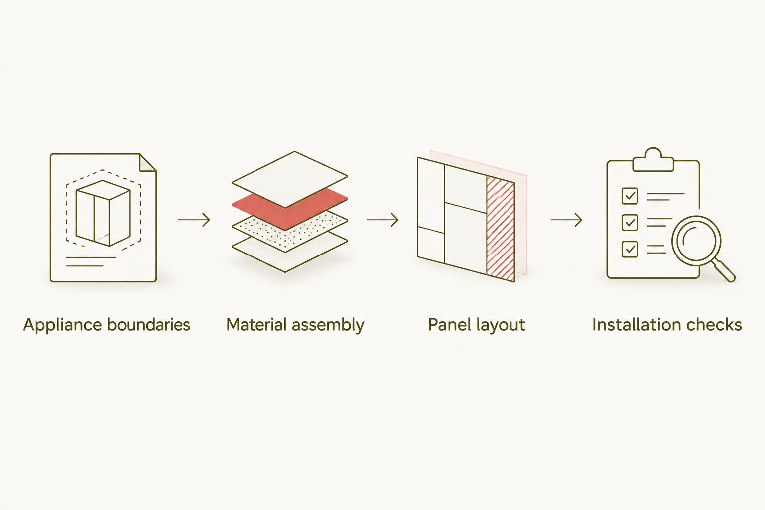
    Workflow from checking fireplace boundaries to reviewing materials, panel layout, and installation

    Material assembly

    Check every layer, not just the surface

    1. Identify the composition of the visible panel and everything behind it. Include felt, MDF, wood, plastic, adhesive, battens, insulation, and existing wall finishes where present.
    2. Match the proposed assembly to the appliance’s facing requirements. If the manual calls for a particular noncombustible construction, use that construction rather than a visually similar substitute.
    3. Check the adhesive manufacturer’s substrate and temperature requirements. A suitable adhesive does not make an otherwise prohibited panel assembly acceptable.
    4. Resolve conflicting instructions before purchase or cutting. Ask the fireplace manufacturer about the appliance requirements and the panel supplier about the panel’s documented properties.

    Expected result: You have a documented material assembly for each part of the wall, with decorative panels kept outside prohibited areas.

    Compare the finish approaches

    These are layout options, not blanket approvals for any named product. The fireplace instructions decide whether a particular material and installation are allowed.

    Finish approach Best for Benefit Limitation
    Wood decorative panels outside required clearances A warm accent wall beside the fireplace Adds grain and texture Wood remains combustible; projecting edges need checking
    Acoustic panels outside required clearances Rooms where decorative sound absorption is also wanted Combines a patterned finish with acoustic treatment Backing and core need assessment; acoustic performance is not fire approval
    Faux-stone decorative panels outside required clearances A textured feature wall Creates a stone-like appearance Appearance does not establish noncombustibility or heat suitability
    A documented noncombustible facing assembly permitted by the manual The appliance’s designated facing area Meets the specified facing approach when correctly built Substrate, attachment, thickness, and joints still need to match the instructions

    Never classify faux stone, PVC, or a coated panel by appearance. A stone-like surface does not prove the underlying product is suitable next to a fireplace.

    Keep performance claims in their proper category

    The Panel Hub describes its real wood acoustic panels with an NRC 0.85 rating, a 5-year warranty, and installation in under 2 hours. Those claims address sound absorption, warranty coverage, and installation speed; none establishes fireplace clearance or approval for a heated surround.

    NRC describes sound absorption, not resistance to ignition. A warranty is not a fire classification, and a general installation-time claim is not a schedule for a fireplace renovation.

    For your 2026 material selection, ask for the exact product’s documentation rather than extending a general brand claim to every panel. Approve the assembly first; choose the decorative pattern second.

    Panel layout

    Dry-fit the decorative boundary

    1. Measure the wall only after establishing the fireplace boundaries. Mark the proposed panel edges without fastening anything.
    2. Dry-fit the panel arrangement, accounting for backing, battens, trim, and adhesive thickness. Position full panels and cuts so no layer crosses the permitted boundary.
    3. Check the complete glass-removal and service-access procedure against the mock-up. Keep controls, switches, and access doors usable without dismantling fixed paneling.
    4. Plan how the decorative finish ends beside the approved facing. Follow the material instructions for joints and movement; do not fill a required opening with trim or sealant.

    Expected result: The mock-up shows a finished wall that respects the clearance map and still allows the appliance to be operated and serviced.

    A symmetrical layout is a design preference, not a reason to move the panel boundary inward. If the clearance map leaves unequal wall areas, adjust the decorative pattern rather than the safety limit.

    A 2026 layout drawing should show panel depth as well as panel width. That makes a projecting slat, thick edge trim, or added mounting batten visible before installation.

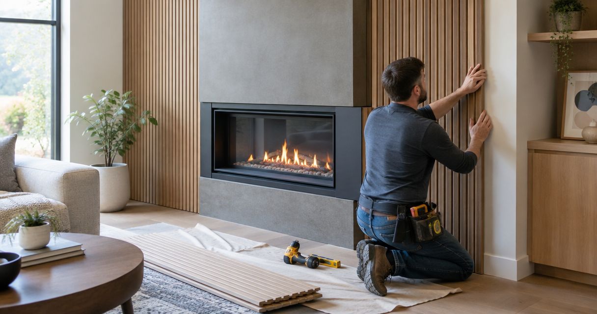
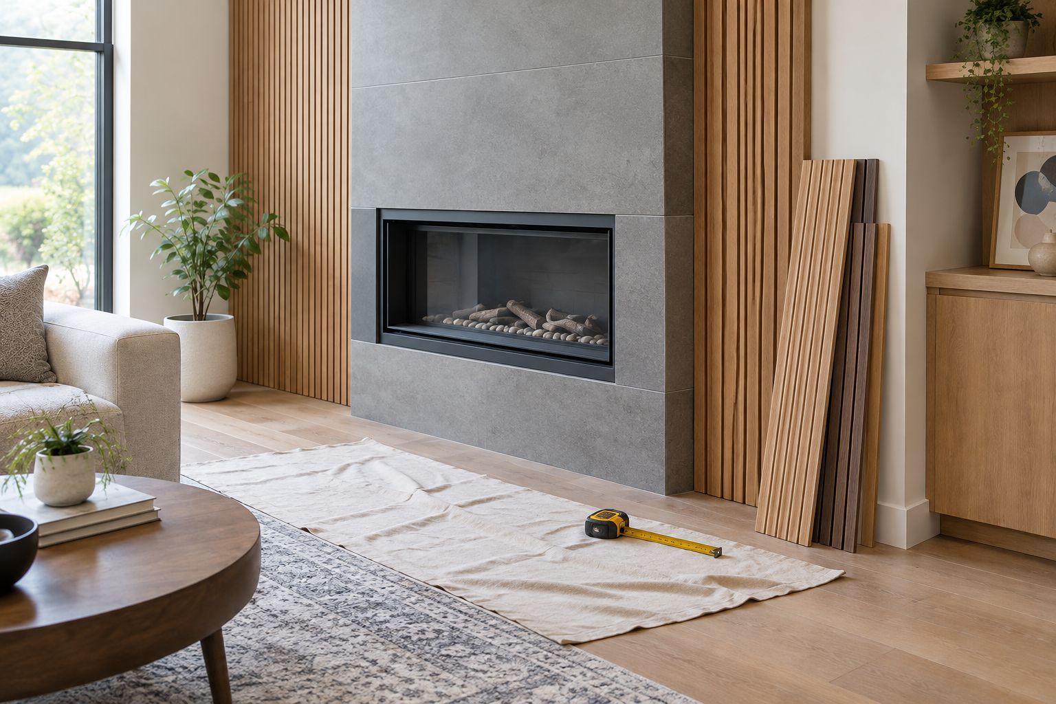
    Wood panel samples dry-fitted beside a tiled fireplace surround

    Installation checks

    Fasten panels without changing the appliance

    1. Confirm the wall substrate is suitable for the panel attachment method. Identify concealed services before drilling, and do not drill into the fireplace enclosure or chase without a verified fastening plan.
    2. Install the decorative panels according to their instructions and the approved layout. Keep battens, adhesive, trim, and panel edges out of prohibited areas.
    3. Leave ventilation and service openings unchanged. Do not bridge an opening with decorative mesh, felt, a removable-looking strip, or a panel offcut.
    4. Complete any required professional review or inspection before operating the fireplace. Have a qualified professional address changes involving the appliance, gas supply, venting, or electrical connections.
    5. Before returning the appliance to use, confirm service access and follow its operating instructions. Check that required smoke and carbon monoxide alarms are installed and maintained according to their instructions and local requirements.

    Expected result: The panels are secure, the appliance’s required openings remain clear, and the installation has received any required checks before use.

    Do not run the fireplace to discover whether a questionable material survives. A heat check can help investigate a problem, but it cannot replace the specified clearances or establish that an unapproved assembly is safe.

    Photograph the finished boundaries for your 2026 home-maintenance records. Keep panel instructions, adhesive information, and inspection records with the fireplace documents.

    Update an existing paneled fireplace wall

    An existing installation needs a condition check before a cosmetic refresh. Keeping the old panel boundary does not establish that the original arrangement was correct.

    1. Identify the appliance and retrieve its exact instructions.
    2. Compare the existing surround, panel depth, air openings, and access points against the required arrangement.
    3. Look for discoloration, warped panels, softened adhesive, loose trim, or damaged backing. Stop using the fireplace and arrange a qualified inspection when you find heat-related damage.
    4. Have prohibited or damaged materials removed through an appropriate repair plan, then rebuild the decorative wall outside the documented limits.

    Best for: Homeowners changing an accent wall without replacing the fireplace. The benefit is a focused refresh; the limitation is that concealed construction or an incorrect existing surround can require more than new panels.

    Do not layer new panels over old finishes simply to hide damage. Added thickness changes the finished geometry, and covered damage becomes harder to inspect.

    Troubleshooting

    The manual and the current surround do not match

    Pause the panel installation. Have a qualified fireplace professional check the appliance and existing construction. Do not preserve an incorrect condition because it predates your project.

    The panel edge clears the opening, but the trim projects inward

    Recheck the projection requirements using the finished trim position. Move the decorative boundary or choose a different edge detail that complies; checking the flat panel alone is insufficient.

    The facing looks like stone, but its composition is unclear

    Obtain the product’s material and fire-test documentation. Until the required properties are established, do not use it where the appliance requires noncombustible facing.

    Glass or controls become inaccessible after dry-fitting

    Change the layout before fastening panels. Follow the appliance’s service procedure; a panel that can theoretically be removed is not a substitute for the specified access arrangement.

    Panels discolor, warp, or release an unusual smell during use

    Stop operating the fireplace and arrange a qualified inspection. Do not add insulation, sealant, or a homemade heat shield as a repair without an approved design.

    Customize your workflow

    Extend the approved layout across the room, not toward the firebox. Use wood texture on adjacent walls and keep the appliance-facing area distinct where its instructions require a different assembly.

    The Panel Hub decorative wall panels give you choices for the outer feature wall, but each selected panel still needs its own material review. Avoid treating an acoustic backing or a geometric surface as interchangeable with another construction.

    If the room also has another heating source, review the separate workflow for wall panels with baseboard heating. Fireplace clearances do not establish the requirements for another heater.

    FAQ

    Can I install wood wall panels around a gas fireplace?

    Yes, where the exact fireplace instructions permit combustible finishes. Check panel depth, backing, battens, trim, and adhesive, and keep the complete assembly outside prohibited areas.

    How far should wall panels be from a gas fireplace?

    Use the clearances stated for your exact fireplace model. There is no universal distance that covers every appliance, side wall, mantel projection, and finishing arrangement.

    Can acoustic wall panels go above a gas fireplace?

    Only where the appliance instructions permit the complete acoustic-panel assembly. A sound-absorption rating does not establish fire safety, and backing or projecting slats require their own checks.

    Are faux-stone wall panels safe for a fireplace surround?

    A stone-like appearance does not establish fireplace suitability. Verify the panel composition and documented properties against the appliance’s facing requirements before using it.

    Does cement board let me put wood panels closer to the fireplace?

    Cement board does not automatically reduce required combustible clearances. Use only an assembly expressly permitted by the fireplace instructions and applicable local requirements.

    Can I glue panels directly onto the fireplace enclosure?

    Do not attach panels to the enclosure unless the appliance instructions expressly permit that attachment and material assembly. Adhesive suitability alone does not authorize covering the appliance.

    Do I need a professional to install panels around a gas fireplace?

    Use a qualified fireplace professional for appliance identification, unclear clearance requirements, existing heat damage, or changes involving gas, venting, or electrical connections. Handle decorative panel work only within a verified installation plan and local requirements.

    One last thing

    The hidden layer can determine whether the visible finish is acceptable. A permitted facing surface does not automatically make combustible battens, backing, or adhesive acceptable beneath it.

    Before fastening the first panel, trace every layer from the room-facing surface back to the wall. If one layer lacks the required documentation, resolve that layer before completing the surround.

    Related guides

  • Wiring outlets behind wood wall panels: 2026 workflow

    Wiring outlets behind wood wall panels: 2026 workflow

    Instead of repeatedly trimming panels around a recessed outlet, plan wiring outlets behind wood wall panels with an electrician before you cut: establish the finished wall depth, bring the electrical enclosure to the wood surface, and keep every connection accessible. This 2026 workflow separates your panel-fitting work from the electrical work so the finished wall looks intentional without concealing a hazard.

    TL;DR
    • Wiring outlets behind wood wall panels requires accessible electrical boxes, suitable enclosure depth, and protected cable routes.
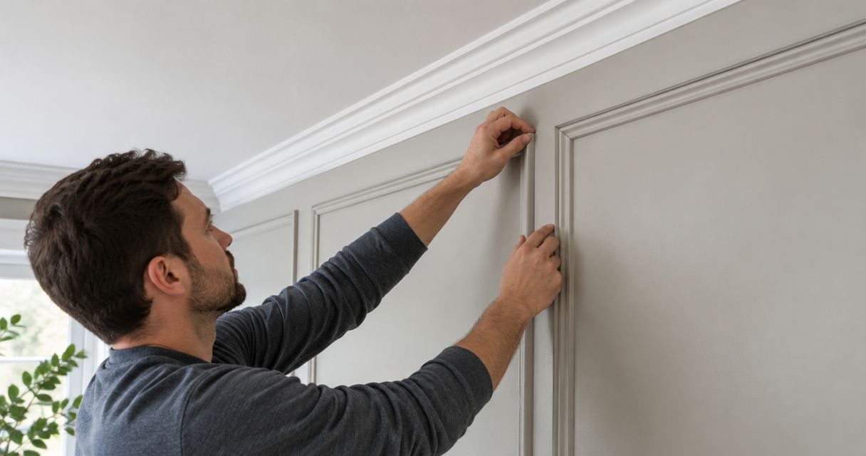
    • The Panel Hub wood wall panels suit homeowners planning decorative upgrades; electrical alterations belong with a qualified electrician.
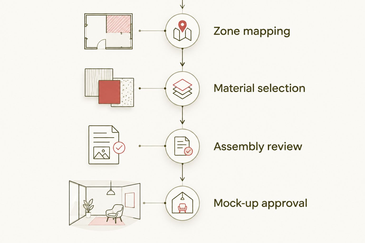
    • Wood is combustible: do not apply the recessed-box allowance used for some noncombustible wall finishes.
    • Dry-fit the panel opening and cover plate before attaching wood slat panels permanently.

    Why this matters

    An outlet that worked correctly before paneling can become incorrectly recessed afterward. Added wood, backing, adhesive, and mounting battens change the finished surface; a longer mounting screw alone does not extend the electrical enclosure.

    The Panel Hub wood wall panels are best for homeowners planning decorative wall upgrades, not a substitute for electrical enclosure protection. Start with your preferred finish from The Panel Hub, then coordinate the outlet detail before installing it.

    For a US project in 2026, the relevant National Electrical Code provisions include Section 314.20 for box position at combustible surfaces, Section 300.4 for protection against physical damage, and Section 314.29 for accessibility. Your local authority determines the adopted edition, amendments, permits, and inspection requirements; the calendar year does not establish which code applies.

    Before you start

    • Arrange electrical access and approval. Book a qualified electrician for enclosure changes, conductor work, testing, and any required inspection. Identify the circuit and arrange a time when it can remain safely isolated.
    • Gather the complete wall assembly. Have a panel sample, any backing or battens, the intended cover plate, a tape measure, a level, marking tools, and appropriate panel-cutting equipment. Obtain the panel manufacturer's installation instructions and the electrical accessory instructions.
    • Check the hidden gotcha: the finished depth is not just the panel thickness. A recessed box behind combustible wood needs a suitable enclosure solution. Uneven slats also need a stable mounting detail; a cover plate cannot replace a box extension or conceal an unsuitable opening.

    Ask the electrician to inspect existing wiring before covering the wall. Damaged insulation, loose boxes, unidentified circuits, or overcrowded enclosures are reasons to resolve the electrical work first, not reasons to hurry the decorative work.

    Choose your outlet workflow

    The right arrangement depends on whether you are preserving the outlet position, moving it, or adding a thicker mounting assembly. These are installation approaches, not interchangeable electrical products.

    Workflow Best for Advantage Limitation
    Existing outlet position A sound existing circuit and an outlet that remains useful Preserves the room's current outlet layout Added finish depth still requires an enclosure assessment
    Relocated outlet An outlet obstructed by furniture or a planned feature wall Places the outlet where you need it Requires electrical alterations and a plan for the original box
    Batten-mounted panels A panel system installed over a supporting framework Allows the specified panel mounting arrangement Adds depth and creates extra fastening locations near concealed cables

    Keep an existing outlet only when its position and electrical condition suit the finished room. Moving furniture after installation should not leave the only useful receptacle behind a fixed cabinet.

    For your 2026 project plan, record the chosen workflow alongside the panel layout. A decision made on paper is easier to change than an opening cut into finished wood.

    Finished-depth plan

    1. Measure the assembly. Add the thicknesses of the panel, backing, battens, and any other specified layers. Use the actual materials rather than an assumed catalog dimension.
    2. Locate the boxes. Mark each existing outlet and any other electrical enclosure on your wall drawing. Include junction boxes that do not contain a receptacle; those still need access.
    3. Choose the cover-plate landing. Position the outlet where its plate can sit properly on the intended finished detail. With slats or textured wood, discuss a flat mounting detail before committing to the pattern.
    4. Agree on the enclosure solution. Have the electrician select a listed box extension or a box repositioning arrangement suitable for the existing box and new surface. Do not assume every extender fits every enclosure.

    Expected result: you have a measured wall build-up, marked box locations, and an agreed outlet detail before cutting any panels.

    At a combustible wood surface, NEC Section 314.20 requires the box, extension ring, or listed extender to reach the finished surface or project beyond it. Treat 0 inches of setback as the planning limit for the enclosure edge at that wood surface; this is not the same as the position of the receptacle face.

    Do not borrow the recessed-box allowance that applies to qualifying noncombustible finishes. Wood veneer over another material does not justify treating the exposed wood as noncombustible.

    Circuit and enclosure preparation

    1. Have the electrician isolate the circuit. The electrician should prevent inadvertent reenergizing and verify the absence of voltage with appropriate equipment. An outlet that stops powering a lamp is not sufficient verification.
    2. Inspect the existing enclosure. Have the electrician check box security, conductor condition, grounding, available conductor length, and box-fill requirements before specifying an extension or relocation.
    3. Approve the cable route. For a new or moved outlet, the electrician should plan the route and protective measures before panel attachment. Do not place loose household cords behind permanently attached panels.
    4. Mark fastening restrictions. Transfer the electrician's cable-route information to the installation plan so panel screws and batten fasteners avoid those locations.

    Expected result: electrical preparation is complete to the stage required for panel fitting, and you know where not to drill or screw.

    NEC Section 300.4 includes a 1¼-inch clearance requirement from relevant framing edges for certain concealed cable routes, with protective measures where that clearance cannot be maintained. A stud finder does not establish that every cable meets this clearance.

    For the bored-hole framing condition covered by Section 300.4(A)(1), a steel protective plate is generally at least 1/16 inch thick, subject to the provision's exceptions for listed alternatives. Have the electrician specify protection; do not add arbitrary metal scraps or drive panel fasteners through protective plates.

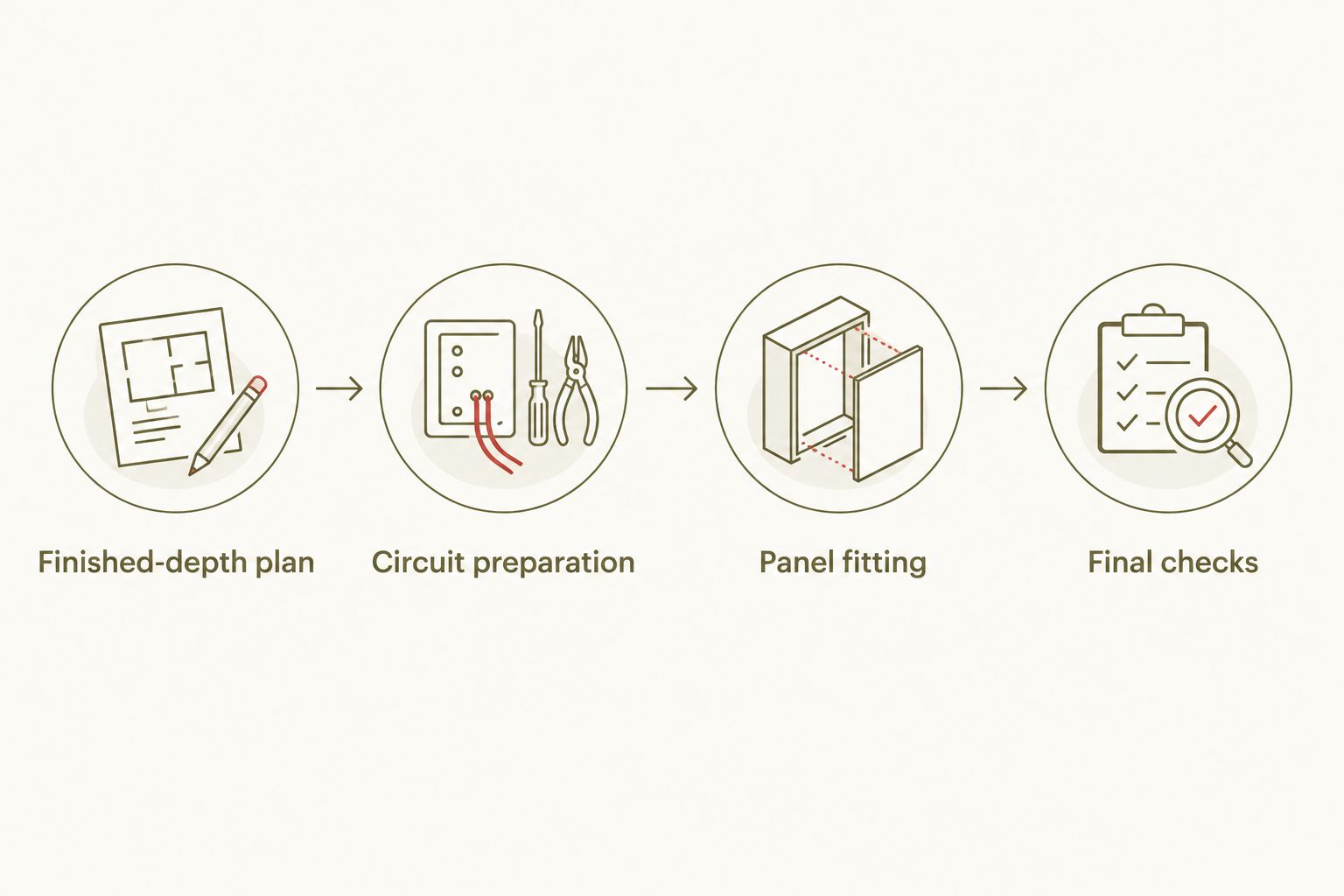
    Sequence from finished-depth planning through circuit preparation, panel fitting, and final checks
    Resolve enclosure depth and cable protection before attaching the finished panels.

    Panel fitting

    1. Transfer the opening to the detached panel. Measure from fixed reference points, checking orientation and the direction of the panel pattern. Mark the opening required by the agreed enclosure detail, not just the visible receptacle face.
    2. Cut away from the wall. Support the detached panel on a suitable work surface and use the manufacturer's recommended cutting method, eye protection, and dust controls. Never plunge a saw into the installed wall around concealed wiring.
    3. Dry-fit the panel and plate. Check the opening against the prepared enclosure, with electrical components handled by the electrician. Confirm that the intended plate covers the perimeter and has an appropriate landing surface.
    4. Attach the panel without obstructing access. Follow the panel installation instructions and fastening restrictions. Keep adhesive, dust, and wood offcuts out of the electrical enclosure, and leave electrical mounting points unobstructed.

    Expected result: the panel opening fits the enclosure detail, the plate has a suitable landing, and the electrical box remains accessible without removing permanent paneling.

    The cover plate should not serve as a clamp to bend slats flat. Likewise, an oversized plate is not a repair for an opening that leaves an unsafe gap or exposes combustible material inside the enclosure boundary.

    Where the panel pattern has raised and recessed areas, test the actual plate against a sample. A pattern that looks flat from across the room can leave the plate rocking at the wall.

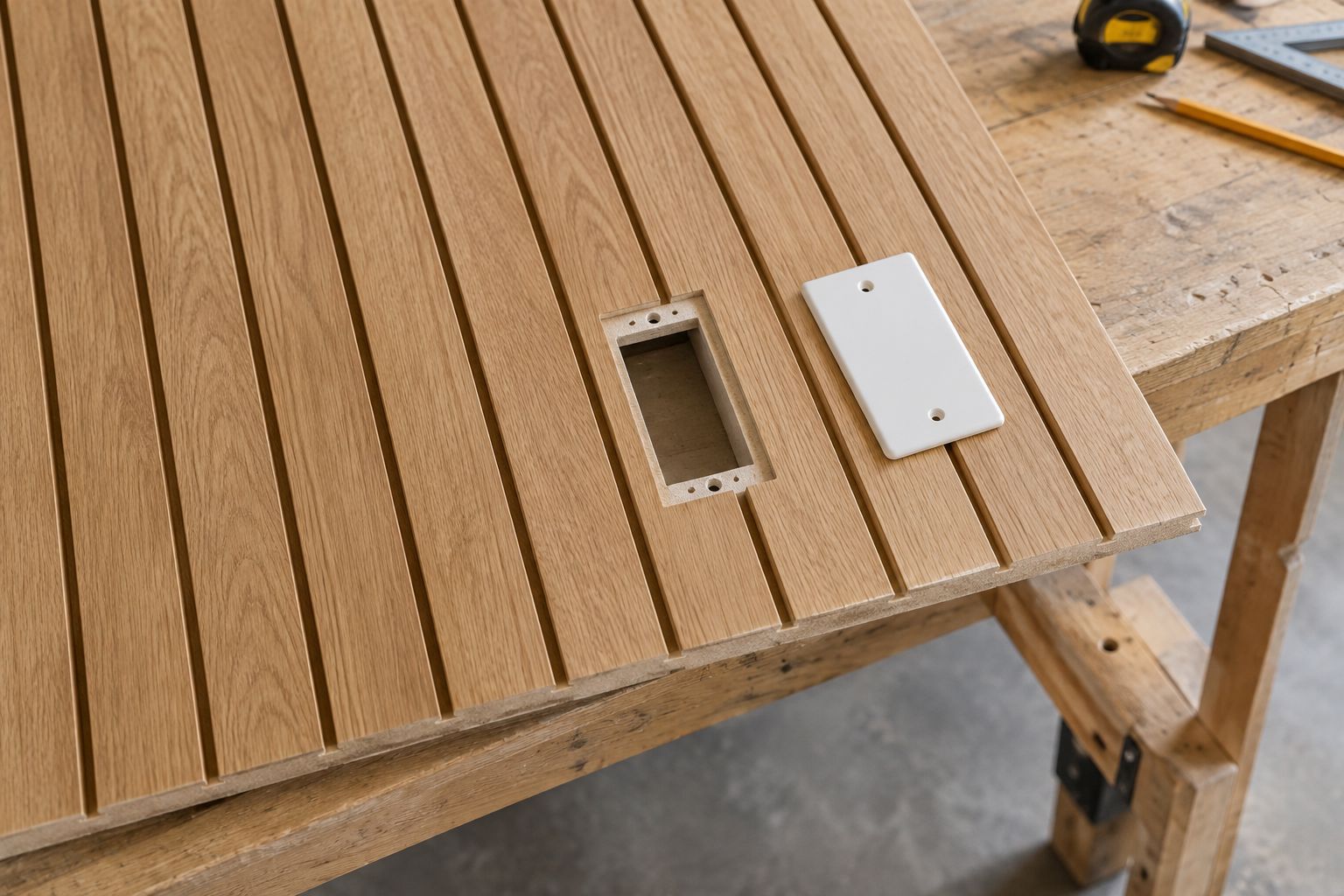
    Detached wood slat panel with an outlet opening and a cover plate ready for dry fitting
    Cut and check the detached panel before attaching it near concealed wiring.

    Leave final electrical assembly to the electrician. Your panel-fitting milestone is a clean, correctly located opening—not a powered outlet.

    Final checks

    1. Have the electrician complete the device installation. The electrician should confirm the selected mounting hardware, device support, conductor connections, grounding, and enclosure arrangement meet the applicable requirements and accessory instructions.
    2. Check the finished plate. Confirm it is secure, sits properly, and leaves no exposed conductors. Do not tighten it excessively to compensate for an uneven panel surface.
    3. Complete electrical testing and inspection. Have the electrician verify operation and any required protective-device function before the circuit returns to normal use. Complete the local inspection process where required.
    4. Save the installation record. Keep photographs of cable routes, protective plates, and box locations before they are concealed, together with the panel and electrical accessory instructions.

    Expected result: you have a finished outlet that is supported, enclosed, accessible, and checked—not merely one that powers a device.

    For your 2026 installation record, note who completed the electrical work and which wall areas contain concealed routes. Photographs support future planning, but they do not replace professional checks before later drilling.

    Second workflow: move the outlet before paneling

    Best for: an existing outlet that will sit behind fixed furniture or interrupt the planned feature wall. Relocation addresses usability, but it adds electrical work and changes the treatment of the original box.

    Have the electrician establish the new position, circuit suitability, cable route, enclosure depth, and local approval requirements before you order custom cuts. Then use the same finished-depth and dry-fitting sequence for the new location.

    The original box cannot simply disappear behind permanent wood if it still contains connections requiring access. NEC Section 314.29 governs accessibility; the electrician must either provide compliant access or remove the need for that junction through a suitable rewiring arrangement.

    Do not run a standard extension cord behind the panels to imitate a relocated outlet. For a wall-mounted television or desk, ask the electrician to plan power separately from signal cables, including any required separation and suitable cable types.

    Troubleshooting

    • The receptacle appears recessed after paneling. Stop final assembly and have the electrician reassess the complete finish depth. Longer screws or device spacers alone do not bring the enclosure edge to the combustible surface.
    • The plate rocks against the slats. Revisit the flat landing detail and panel cutout. Do not bend the plate or crush the wood by overtightening its screw.
    • The cutout is too large. Stop before attaching the panel permanently. Replace or rework the affected piece using an approved detail; a decorative cover must not hide an unresolved enclosure problem.
    • A planned screw position meets a protective plate. Move the fastening position or revise the attachment method with the installer. Never drill through the plate to reach the stud.
    • A cable or junction box appears during preparation. Pause the panel installation and have the electrician identify it. Keep the box accessible and resolve the route before closing the wall.

    Customize your workflow

    Plan every outlet on the wall together, including switches and blank-covered junction boxes. Repeating one checked mounting detail can simplify the decorative layout, but the electrician still needs to assess each enclosure individually.

    For your 2026 room upgrade, decide furniture placement before outlet placement. In a bedroom, consider bedside access; in a home office, map the desk and equipment positions without routing everyday power cords behind permanent cladding.

    The Panel Hub wood wall panels can provide the decorative finish around this plan. Their panel characteristics do not establish electrical approval for the surrounding installation, so keep finish selection and electrical acceptance as separate decisions.

    FAQ

    Can I install wood wall panels around existing outlets?
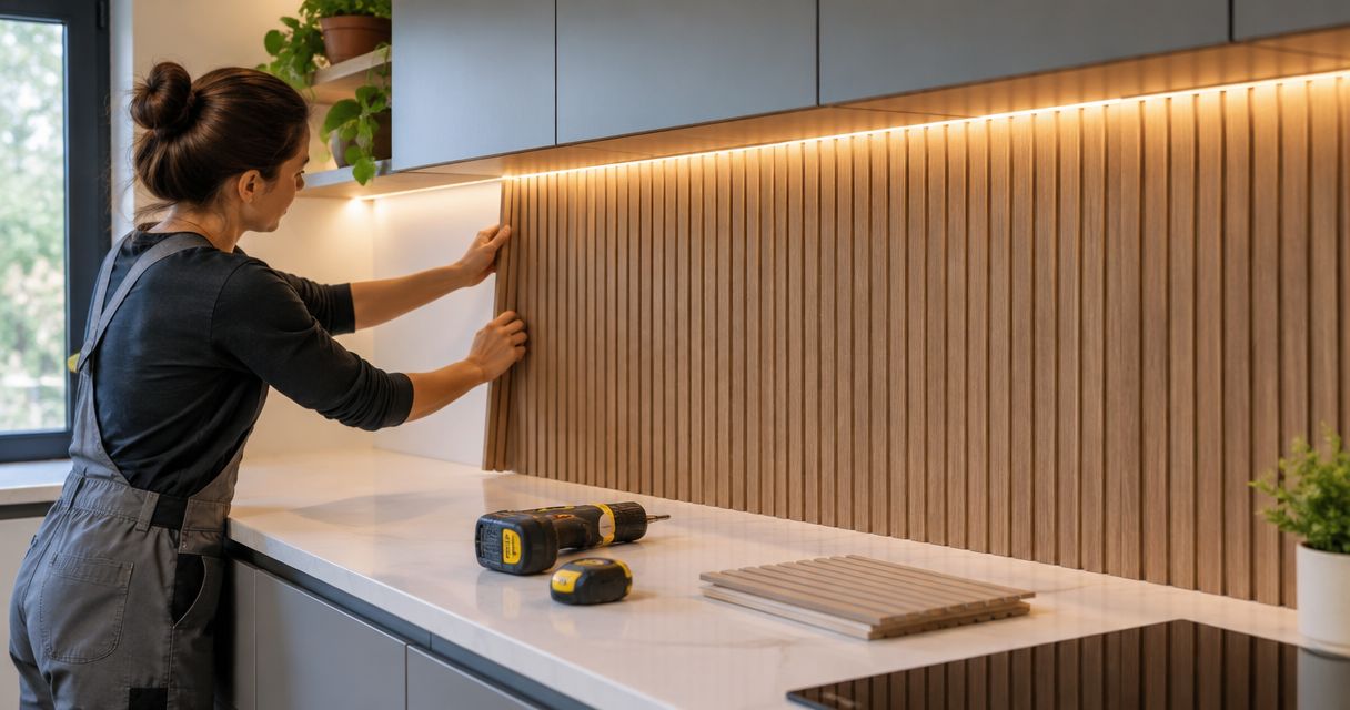
    Yes, provided the electrical enclosure, device mounting, cover plate, and access remain compliant after the added finish. Have an electrician assess the new wall depth before attaching the panels.

    Do I need a box extender behind wood wall panels?

    You need an enclosure arrangement that reaches the combustible finished surface or projects beyond it. An electrician can determine whether a suitable listed extender or box repositioning is appropriate.

    Can I just use longer outlet screws?

    No, longer screws alone do not extend the electrical enclosure. They cannot substitute for the required enclosure detail at a combustible wood surface.

    Can I hide an unused junction box behind paneling?

    Not if it contains connections that must remain accessible. Have an electrician provide compliant access or rework the wiring so the concealed junction is no longer needed.

    Can I run an extension cord behind a wood feature wall?

    Do not use an ordinary extension cord as concealed permanent wiring behind wood panels. Have an electrician install a suitable permanent power arrangement instead.

    Are acoustic wood panels different around outlets?

    Acoustic wood panels still require an appropriate electrical enclosure and accessible connections. Slats, backing, and any battens must all be included when establishing the finished wall depth.

    Which electrical code applies to my 2026 panel installation?

    The code edition adopted by your local authority applies, including local amendments. Ask your electrician or building department about permits and inspections before changing wiring or outlet locations.

    One last thing

    A working outlet is not proof of a finished electrical installation. A receptacle can power a lamp while its box remains incorrectly recessed behind combustible wood.

    Before calling your The Panel Hub wall-panel project complete, check the enclosure detail—not just the cover plate's appearance. That small check belongs before the wall becomes difficult to reopen.

    Related guides

  • Wiring smart switches behind wall panel installations

    Wiring smart switches behind wall panel installations

    Instead of repeatedly removing trim to fix a buried switch, plan wiring smart switches behind wall panels around an accessible electrical box, a supported switch, and the finished wall depth. Complete and test the electrical work before fitting decorative panels, then keep the switch and its connections accessible through the removable faceplate.
    TL;DR
    • Wiring smart switches behind wall panels requires accessible electrical boxes, not connections hidden behind decorative cladding.
    • The Panel Hub wall panels suit homeowners updating decorative walls; electrical compatibility depends on the switch and installation.
    • Confirm neutral requirements, load compatibility, and finished wall depth before cutting panels.
    • Have an electrician handle wiring changes, box extensions, and unfamiliar multi-location circuits.

    Why this matters

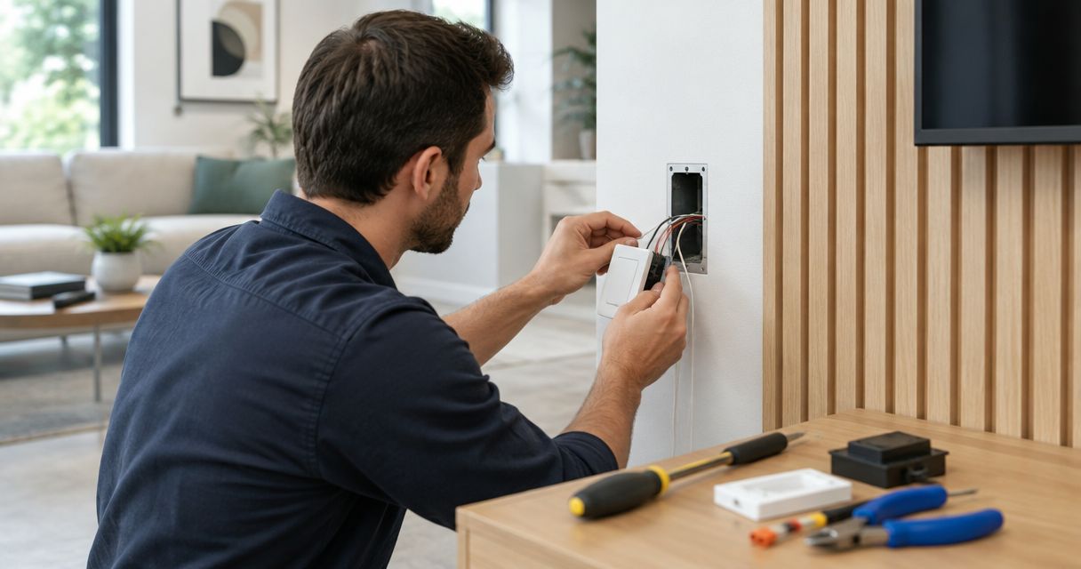
    A decorative wall changes the surface around a switch. It does not turn the space behind the panels into an approved electrical enclosure. Keep every wiring connection inside an appropriate box, and keep that box accessible without damaging the wall finish.

    The Panel Hub is best for homeowners choosing decorative wall panels, not for determining smart-switch electrical compatibility. When planning your The Panel Hub installation, treat the panel layout and electrical layout as separate decisions that must meet at the same finished surface.

    For a 2026 renovation, the key question is not whether a switch looks flush. It is whether the box, mounting arrangement, wiring, and connected light meet the device instructions and locally adopted electrical requirements.

    Before you start

    • Gather the actual specifications. Have the smart-switch installation manual, light or driver specifications, panel thickness, backing details, and proposed faceplate. Arrange a qualified electrician for wiring changes and confirm local permit requirements.
    • Confirm access and connectivity. You need access to the circuit breaker and, for connected functions, the manufacturer's required app, account, hub, or wireless network. Identify whether the light operates from one location or multiple locations.
    • Check the hidden depth problem first. Added panels and battens move the finished wall forward. A faceplate can conceal a recessed box without making it compliant; select the box-extension arrangement before cutting the panel opening.

    Do not begin by disconnecting wires to discover what they do. If the existing circuit is unfamiliar, have an electrician identify it before purchasing the replacement switch or committing to the panel layout.

    Circuit and switch compatibility

    This first configuration unit decides whether your chosen switch belongs on the existing circuit. Smart switches are not interchangeable simply because their faceplates look alike.

    1. Identify the circuit arrangement. Establish whether the existing control is single-location, multi-location, or part of a dimming system. Have an electrician identify supply, switched conductors, grounding, and any shared-circuit conditions.
    2. Check the neutral requirement. Read the exact switch manual. Some devices require a neutral at the switch box; others use a different approved arrangement. A white conductor alone does not establish that a usable neutral is present.
    3. Match the connected load. Confirm that the device supports the light, LED driver, or other equipment it will control. A lighting switch is not automatically suitable for a fan motor, and a dimmer requires compatible dimmable equipment.
    4. Check voltage and enclosure space. A common US household lighting circuit is 120 volts, but the electrician must confirm the actual supply and device rating. Confirm that the box has adequate capacity for the conductors, connectors, grounding, and replacement device.
    5. Confirm the connected features. If the device specifies 2.4 GHz Wi-Fi, check that your network supports that band at the switch location. For a hub-based device, verify the required hub and its compatibility before installation.

    Expected result: You have a supported switch, an identified circuit, and a connection plan taken from the device's own instructions—not a generic wire-color diagram.

    For your 2026 project, retain the exact model instructions with your renovation records. Similar-looking switches can have different neutral, companion-device, and load requirements.

    Finished wall and electrical box

    The finished surface includes everything added over the existing wall: panels, backing, battens, and any mounting layer. Measure that complete assembly rather than relying on the decorative panel thickness alone.

    1. Measure the build-out. Record the distance from the existing wall surface to the proposed finished face. Dry-fit a sample near the switch without opening or disturbing its wiring.
    2. Locate the box opening. Mark the opening independently of the panel pattern. Keep access to the device mounting screws and enough clearance to remove the switch for future service.
    3. Resolve the box position. Have the electrician choose a listed extension, replacement box, or other approved arrangement suited to the existing enclosure and finished material. Do not substitute loose packing pieces for a proper enclosure extension.
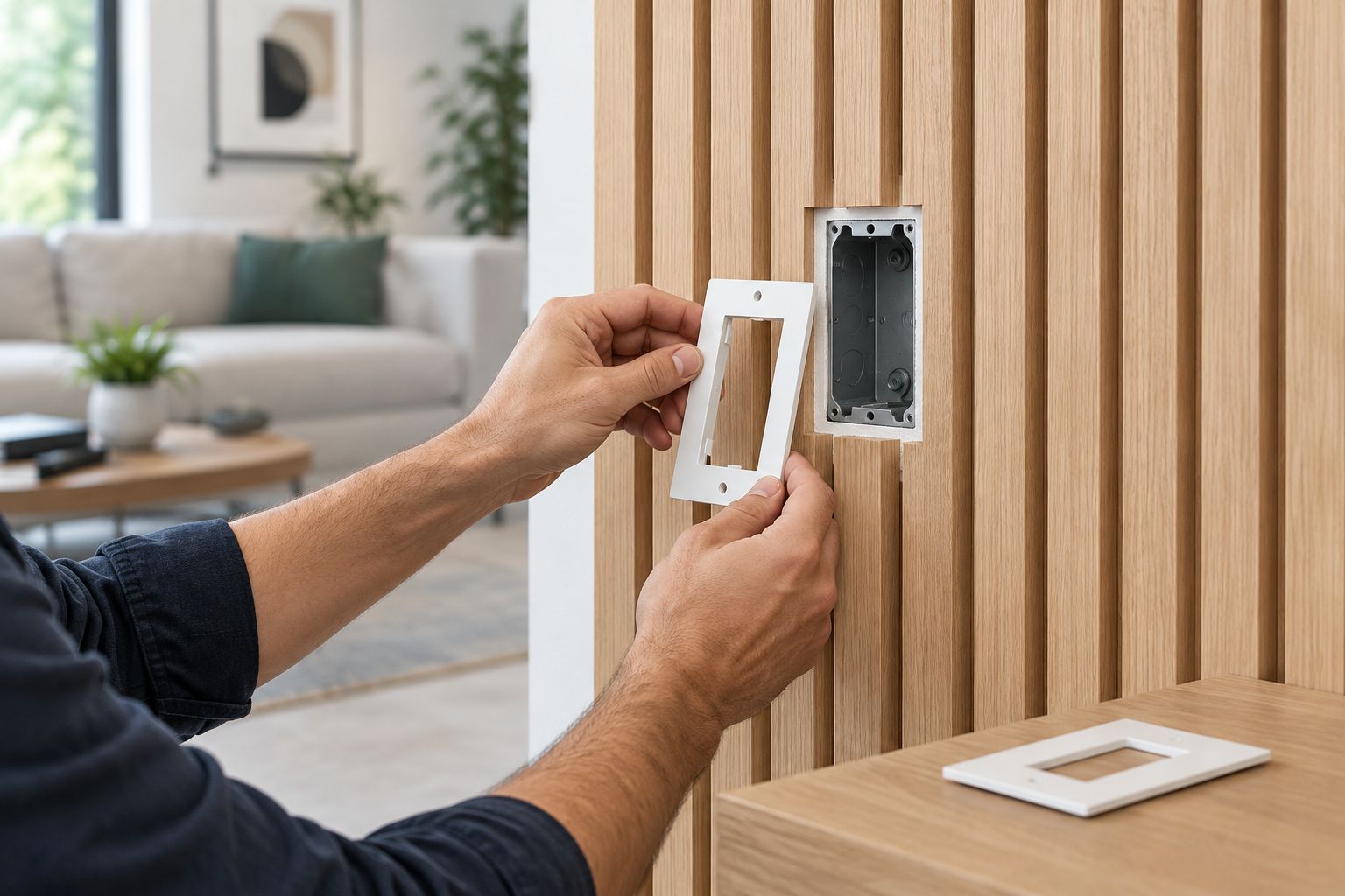
    4. Provide a flat mounting surface. Where slats or raised patterns prevent the faceplate from sitting flat, plan a suitable trim detail or mounting surround. Do not bend the plate across uneven surfaces.
    5. Dry-fit the removable parts. Check that the faceplate comes off without removing glued panels and that no panel edge traps the switch body or wiring.

    US National Electrical Code section 314.20 distinguishes combustible from noncombustible wall surfaces. At combustible surfaces, boxes or appropriate extensions must reach the finished surface or project beyond it. The permitted recess of up to 1/4 inch applies to qualifying noncombustible surfaces; it is not a general allowance for wood paneling. Confirm the locally adopted edition and requirements with your electrician.

    Expected result: The enclosure reaches the required position, the plate has a stable seating surface, and future electrical service does not require cutting the decorative wall.

    Wood slat wall opening with an accessible electrical box and a flat mounting surround
    Plan the mounting surface before cutting the decorative wall.

    A neat opening is only part of the result. The enclosure arrangement must be correct behind it, and the faceplate must remain removable after the surrounding finish is complete.

    Electrical installation and panel fitting

    Electrical verification comes before decorative finishing. A switch that pairs successfully with an app can still have an unsuitable load, inadequate enclosure space, or an incorrect mounting arrangement.

    1. Isolate the circuit. Have the electrician switch off the appropriate breaker, prevent unintended re-energization, and verify absence of voltage with suitable test equipment before handling conductors. A wall switch in the off position does not establish that the box is de-energized.
    2. Complete the approved wiring arrangement. The electrician should follow the device diagram, connector instructions, grounding requirements, and applicable code. Never use the equipment-grounding conductor as a substitute for a neutral.
    3. Inspect before closing the box. Confirm secure terminations, proper conductor placement, adequate enclosure capacity, and the correct box extension. Keep wiring inside the enclosure rather than between the panel and wall.
    4. Test basic operation safely. With the device properly mounted and covered, have the electrician restore power and verify physical switching and supported dimming. Resolve flickering, failure to turn off, or abnormal operation before fitting the panels.
    5. Fit the decorative finish. Isolate the circuit again before work near the box. Cut panels away from installed wiring, keep adhesive out of the enclosure, and protect cables from panel fasteners.
    6. Recheck the completed assembly. Confirm that the faceplate sits securely, the switch operates freely, and the plate can be removed independently of the wall panels.

    Expected result: The switch works physically, the electrical installation remains enclosed and accessible, and the decorative finish does not interfere with operation or maintenance.

    For a 2026 wall-panel project, mark known cable routes before selecting fastening locations. Do not drive screws around a switch box based only on where a cable seems likely to run.

    Connected-control setup

    Configure remote operation only after physical switching passes its checks. The electrical installation must work as intended before an automation is allowed to control it.

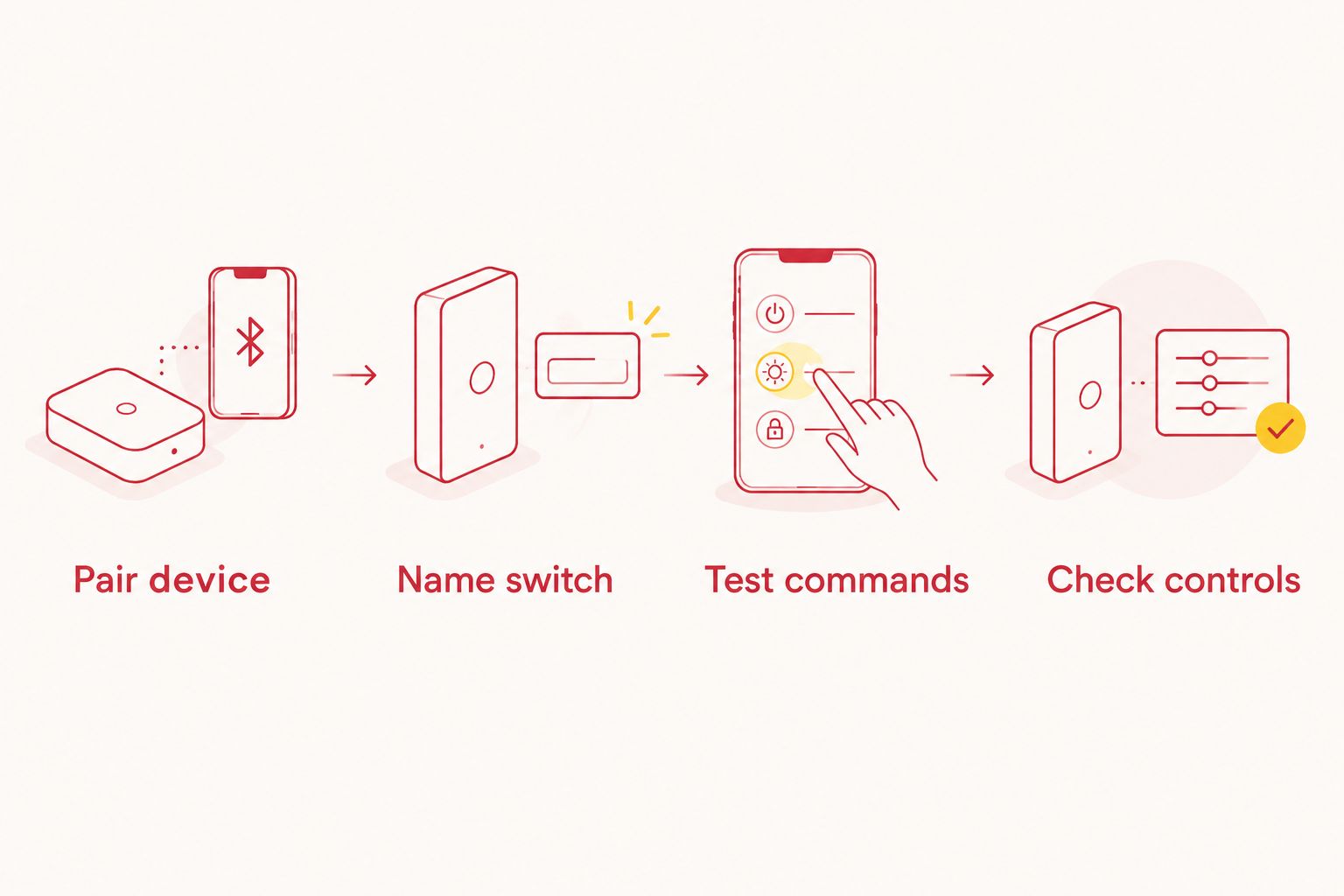
    1. Follow the device's pairing instructions. Use the manufacturer's current app and manual. Follow the exact on-screen labels shown for your model; there is no universal pairing button or reset sequence.
    2. Name the switch by room and function. A name such as Bedroom Accent Light is clearer than a default device identifier. Use a name that distinguishes the switched light from other lights in the same room.
    3. Test commands at the installed location. Verify an on command and an off command. For a supported dimmer, test its approved dimming range and any manufacturer-provided minimum-level adjustment.
    4. Check physical control afterward. Operate the wall switch again after pairing. Confirm that remote commands do not prevent ordinary use by someone without the app.
    5. Create one simple routine first. Start with a supported schedule or scene, then verify its behavior before adding more conditions. Check what happens after a power interruption using the manufacturer's documented settings.

    Expected result: Physical and remote controls behave consistently, and the first routine performs the intended action without competing commands.

    Connected-control setup from pairing the device to checking physical controls
    Test ordinary wall-switch operation after setting up remote control.

    Keep your 2026 setup simple until the completed wall is in place. Test connectivity again after installation rather than treating an earlier pairing test as the final check.

    Second workflow: multi-location control

    If you control the same light from different positions, use the smart-switch manufacturer's approved multi-location arrangement. Do not assume an existing conventional switch can remain connected unchanged.

    Workflow Best for Advantage Limitation
    Single-location smart control A light controlled from one wall position One physical control location to configure Does not add another physical control point by itself
    Approved multi-location smart control A light controlled from several wall positions Preserves convenient control around the room Requires the exact wiring and companion arrangement supported by the manufacturer

    Have the electrician identify the circuit and confirm which device belongs at each location. Check every affected box for neutral requirements, capacity, and panel build-out—not only the box receiving the main smart device.

    After installation, test each physical control separately, then test remote operation. Finish the paneling only after every location works. The Panel Hub wall panels are the decorative finish; they do not determine which multi-location electrical arrangement is supported.

    Troubleshooting

    The faceplate rocks or leaves an uneven gap

    Check whether raised slats or a textured surface prevent flat seating. Plan a flat surround and have the electrician verify the device mounting and box extension. Tightening the plate harder is not the fix for an uneven wall.

    The switch cannot pair after panel installation

    Confirm the device's required network or hub, then check connectivity at the finished wall. Follow its documented recovery procedure. Do not open an energized box to troubleshoot wireless reception.

    The LED light flickers or does not turn fully off

    Have the electrician check load compatibility and wiring against the switch instructions. For a compatible dimmer, use only the manufacturer's documented adjustment process. Do not add an unspecified component behind the panels to mask the problem.

    One multi-location control stops working

    Recheck the approved companion arrangement and circuit identification. Similar-looking controls do not establish compatibility. Isolate the circuit and return the wiring diagnosis to the electrician.

    The switch smells hot, discolors, buzzes abnormally, or trips the breaker

    Stop using the circuit and have it inspected. If safe, turn off the affected breaker; smoke or fire requires emergency action. Do not dismiss these signs as a normal consequence of fitting wall panels.

    Customize your workflow

    Once the electrical installation is complete, improve how the room works. Use a supported schedule for predictable lighting, retain clear physical control, and choose panel joints that make the switch surround look intentional.

    For a 2026 bedroom update, plan the light, switch, and feature wall together rather than letting the panel pattern dictate electrical access. The wall panels for DIY beginners guide helps you continue the decorative planning without confusing panel fitting with electrical work.

    Keep the circuit identification, switch model, and installation instructions with your home records. Photograph the finished box arrangement while the circuit is safely isolated and before the decorative trim conceals its edges.

    FAQ

    Can I hide a smart switch behind wood wall panels?

    Do not bury a conventional wall-mounted smart switch or its electrical box behind permanent paneling. Keep the control usable and the enclosure accessible without damaging the wall finish.

    Do smart switches need a neutral wire?

    Some smart switches require a neutral, and others use a different approved arrangement. Check the exact model instructions and have an electrician identify the conductors; wire color alone is not sufficient.

    Do I need a box extender when adding wall panels?

    You need an enclosure arrangement that meets the requirements at the new finished surface. Added wall depth frequently requires an appropriate extension or replacement box, which an electrician should select for the installation.

    Can a smart switch work with wood slat panels?

    A smart switch can be installed at a wood slat wall when its enclosure, mounting, wiring, and connected load are suitable. Provide a flat faceplate seating area and preserve access to the electrical box.

    Can I keep my existing switch at the other end of the room?

    Keep it only if the smart-switch manufacturer explicitly supports that multi-location arrangement. Some devices require a specific companion control or different wiring, so have the circuit checked before installation.

    Should I pair the smart switch before installing the panels?

    Test physical operation and pairing before finishing the decorative wall, then test connectivity again after the panels are installed. Early testing helps separate electrical or setup faults from problems introduced during finishing.

    Can acoustic wall panels make electrical wiring safer?

    Acoustic performance does not establish electrical safety or suitability as an enclosure. The Panel Hub acoustic wall panels remain decorative materials; compliant boxes, wiring, mounting, and access are separate requirements.

    One last thing

    A larger faceplate does not correct a recessed electrical box. It can hide the opening while leaving the underlying mounting problem unchanged. Before you admire the finished feature wall, confirm that the enclosure—not just the plate—meets the finished surface correctly.

    Related guides

  • Combining wall panels with radiant floor heating

    Combining wall panels with radiant floor heating

    Instead of choosing wall panels and radiant floor heating separately and fixing awkward junctions later, plan the floor edge, wall finish, and heating controls together before installation. Combining wall panels with radiant floor heating works when the floor system, panel material, and installation details meet their manufacturers’ requirements; decorative wall panels are not part of the heating system.

    TL;DR
    • Combining wall panels with radiant floor heating requires coordinated floor edges, panel fastening, and thermostat placement.
    • The Panel Hub suits homeowners adding acoustic wall panels or decorative wood finishes to rooms with radiant floor heating.
    • Keep floor movement joints clear and protect heating cables, tubing, and sensor wiring during installation.
    • Confirm material requirements before installation; a decorative or acoustic rating does not establish heat compatibility.

    Why this matters

    Radiant floor heating warms the room from the floor assembly. Wall panels finish a different surface, but the two installations meet at the baseboard, door trim, and corners. Those junctions deserve a drawing before either installer starts.

    The Panel Hub is best for homeowners adding decorative or acoustic wall panels to an interior upgrade, not for specifying radiant heating equipment. Use The Panel Hub to explore the wall finish, then have the heating installer confirm the heating design independently.

    For your 2026 renovation, separate appearance, acoustics, and heating performance. A warmer-looking wood wall does not establish better heating efficiency, and an acoustic panel does not stop heat loss through an inadequately insulated building envelope.

    The brand describes acoustic panels rated NRC 0.85. NRC measures sound absorption, not thermal resistance or heat tolerance. That distinction prevents an attractive product specification from answering the wrong installation question.

    Before you start

    • Gather the installation documents. Have the exact wall panel instructions, radiant heating instructions, and floor covering instructions. Confirm adhesive requirements, substrate preparation, movement joints, and any operating limits before cutting materials.
    • Arrange the right access and help. You need access to the wall, floor perimeter, thermostat, and heating documentation. Have a qualified heating installer handle system design and commissioning; electrical connections require an appropriately qualified electrician.
    • Identify the hidden fastening risk. Heating cables or tubing, perimeter supply routes, and floor sensor wiring can occupy areas you intend to drill or trim. Obtain the installation layout and photographs before fixing baseboards or low-level battens. Never treat an apparently empty floor edge as proof that drilling is safe.

    Keep these 3 installation documents together throughout the project. A wall panel instruction cannot override a floor movement requirement, and a heating instruction cannot establish that a particular panel adhesive suits the wall substrate.

    Room and material plan

    Choose the wall finish for its actual job

    Start with what you want the room to do. Acoustic treatment belongs in rooms where reflected sound is the problem; decorative relief belongs where texture and pattern are the priority. Neither choice replaces the floor heating specification.

    These two options serve different wall-design goals. Their product descriptions do not establish approval for every heated-room installation, so confirm the relevant conditions before ordering.

    Wall panel option Best for Main benefit Limitation to resolve
    Acoustic Slat Wood Wall Panels | SoundPanel™ Living rooms or bedrooms where sound absorption is part of the brief Combines a slatted wood appearance with an acoustic purpose An acoustic designation does not establish thermal resistance, adhesive compatibility, or heat tolerance
    3D Geometric Pattern Wooden Panels | GroovePanel® Feature walls where solid-wood texture and pattern matter The supplied description identifies real solid wood and a geometric design Solid wood responds to moisture changes; follow the product’s conditioning and installation requirements

    Choose SoundPanel™ for an acoustic brief and GroovePanel® for a decorative brief. Do not choose either as an insulation upgrade without thermal performance documentation.

    For a bathroom, specify a wall system approved for the actual exposure. A heated floor does not turn decorative wood into shower lining, and a decorative panel face does not establish a watertight assembly.

    Establish the room conditions

    1. Confirm that the wall is sound, clean, and suitable for the selected fixing method. Resolve leaks, dampness, loose finishes, and unsuitable coatings before covering the surface.
    2. Complete wet construction work and follow the flooring and panel instructions for drying and conditioning. Do not use the heating system to force materials dry unless the relevant instructions explicitly permit that process.
    3. Check the panel manufacturer’s storage and acclimation instructions. Record the required conditions in your project notes rather than borrowing a timetable from a different product.
    4. Agree on the normal operating conditions with the heating installer. Bring the room into those conditions using the commissioning process required for the floor assembly.

    Expected result: You have a suitable wall substrate and an agreed conditioning plan, rather than panels arriving in a room that is still drying out.

    Floor-edge and fixing plan

    Draw the finished junction

    The wall-to-floor connection is where a good-looking project can become a maintenance problem. Plan the panel bottom, baseboard position, floor expansion detail, and any access requirements as one junction—not separate finishing decisions.

    1. Mark the finished floor level. Use the completed floor assembly height, including its final covering. A mark based on the unfinished substrate gives you the wrong panel starting point.
    2. Mark the panel bottom. Set this position from the panel instructions and chosen trim detail. Keep panels from bearing on the floor unless the complete system specifically requires that arrangement.
    3. Preserve the movement joint. Follow the floor covering manufacturer’s required perimeter detail. Do not bridge or pack that space with panel offcuts, rigid adhesive, or an improvised filler.
    4. Plan the trim. Decide whether the baseboard sits against the panel face or below it. Confirm the fixing method will not pin a floating floor or obstruct required movement.
    5. Mark service access. Keep heating controls, service points, and access covers usable. Design a removable detail wherever maintenance requires access.

    Expected result: Your drawing shows how the wall finish ends without trapping the floor or concealing a service point.

    Planning sequence for the floor level, panel bottom, movement joint, trim, and service access
    Draw the wall-to-floor junction before cutting panels or fixing trim.

    Protect the heating installation

    1. Obtain the heating layout and locate perimeter routes before drilling. Ask the installer to clarify uncertain areas; photographs help document construction but do not replace safe service detection.
    2. Select fixings for the wall substrate and panel system. Do not extend wall-panel fastening into the floor to make a weak fixing feel secure.
    3. Check proposed low-level fasteners against concealed services. Include baseboard fixings, battens, corner trims, and door-stop locations in that check.
    4. Agree on how the heating installer will verify the system after nearby construction work. Use the checks required by the specific electric or hydronic system, not a generic test copied from another installation.

    Expected result: Every fixing location has a safe installation method, and the heating system has a documented verification plan.

    For a 2026 project, retain the final routing record with your renovation documents. The next person fitting a shelf, changing trim, or replacing flooring needs the same information.

    Panel installation and heating handover

    Install the wall finish

    1. Dry-fit the first panel and the bottom trim detail. Check that the layout still works around outlets, switches, corners, and the thermostat.
    2. Cut and prepare panels using the product’s instructions. Keep cutting debris away from exposed heating components and unfinished floor work.
    3. Apply the specified adhesive or install the approved mechanical fixings. Check the adhesive’s substrate suitability and curing conditions; room heat is not permission to shorten its cure.
    4. Fit adjoining panels using the prescribed spacing and joint treatment. Do not tighten joints simply because a smaller gap looks cleaner.
    5. Finish the baseboard and perimeter detail without restraining floor movement. Photograph the completed junction and any concealed fastening arrangements.

    Expected result: The panels are secured to the correct substrate, their joints follow the instructions, and the floor perimeter remains functional.

    A finished room can combine a textured wall with an unobstructed floor edge. The junction should look intentional, but its appearance must follow the technical detail—not replace it.

    Wood-slat feature wall and baseboard meeting a finished living-room floor
    A tidy baseboard detail should preserve the floor’s required movement space.

    The Panel Hub describes quick-install wall paneling projects completed in under 2 hours. That is not a timetable for a combined heating and paneling renovation. Floor preparation, commissioning, material conditioning, and adhesive curing follow separate requirements.

    Complete the heating handover

    1. Have the heating installer complete the prescribed commissioning checks. Confirm that recent trim and panel work has not affected wiring, tubing, sensors, or access.
    2. Keep the thermostat accessible. If panel thickness changes its mounting position, have the installer confirm the revised arrangement rather than surrounding or burying the control.
    3. Confirm the permitted operating settings for the entire floor assembly. Follow the floor covering and heating instructions; there is no single temperature setting that suits every construction.
    4. Record the approved settings and startup procedure. Do not increase the limit to compensate for a room that fails to reach its intended temperature.

    Expected result: You have a functioning heating system, accessible controls, and written operating instructions for the completed room.

    Your 2026 handover should include panel care instructions alongside the heating documents. Clean and maintain the wall finish as its manufacturer directs, without treating it as part of the heating equipment.

    Adding panels when radiant heating is already installed

    An existing heated floor changes the sequence: verify its condition and routing before you begin the wall work. You are protecting a working installation, not coordinating an exposed construction site.

    1. Ask for the existing heating records and operating instructions. Have the system assessed if its condition, routing, or control arrangement is uncertain.
    2. Protect the finished floor using a method suitable for its surface and operating conditions. Do not introduce temporary coverings that conflict with the floor or heating instructions.
    3. Follow panel and adhesive requirements for installation temperature and curing. Agree with the heating installer whether operation needs adjustment during the work.
    4. Install the wall panels and trim without drilling into the floor or disturbing its movement joints. Verify the heating system after the nearby work is complete.

    Best for: A bedroom or living-room refresh where the heated floor is staying in place. The benefit is keeping the existing floor; the constraint is reduced access to concealed services.

    For a 2026 refresh, inspect the existing baseboard detail before copying it. An old junction is not automatically a correct junction.

    Troubleshooting

    • Wood joints open or edges become uneven. Check room moisture conditions, conditioning history, fastening, and movement allowances against the panel instructions. Correct the cause before filling gaps or forcing panels together.
    • The floor edge lifts or feels restrained. Check whether trim, adhesive, or panel bottoms have trapped a floating floor. Have the flooring installer restore the specified movement detail; do not simply add more fixings.
    • Panels loosen after heating startup. Check substrate preparation, adhesive selection, cure conditions, and operating limits. Support loose material safely and follow the panel manufacturer’s repair method rather than applying an unapproved adhesive.
    • The room remains cold. Have the heating installer check controls, sensor behavior, system operation, and the original heating design. Decorative wall panels are not a substitute for correcting an underperforming heating system.
    • A heating fault appears after trim installation. Stop using the affected system and contact the qualified installer. Do not drill exploratory holes or keep resetting a faulting electric system.

    Customize your workflow

    Match the scope to the room. A single acoustic feature wall serves a different purpose from decorative panels around the entire perimeter, and neither scope changes the heating system’s required commissioning process.

    For your 2026 plan, decide which parts you can complete yourself and which need specialist handover. Panel layout and finish selection are separate from electrical connections, heating design, and concealed-service checks.

    Keep 2 checks on your final walkthrough: inspect the visible wall-to-floor junction, then confirm the heating records and controls. A neat room is not proof that hidden work is correct.

    FAQ

    Can I combine wood wall panels with radiant floor heating?

    Yes, provided the wall panels, floor assembly, and installation details meet their respective manufacturers’ requirements. Confirm conditioning, fastening, movement joints, and operating conditions before installation.

    Do acoustic wall panels improve radiant heating efficiency?

    An acoustic rating does not establish improved radiant heating efficiency. NRC describes sound absorption; thermal performance requires separate documentation.

    Should wall panels touch a heated floor?

    Use the panel and floor manufacturers’ specified junction detail, not a universal gap. Keep the floor’s required movement space clear and avoid a panel or trim detail that restrains it.

    Can I drill near the edge of a radiant heated floor?

    Do not drill until concealed heating components and other services have been safely located. Perimeter tubing, cables, and sensor routes can conflict with trim fasteners.

    Should I turn off radiant heating while installing wall panels?

    Follow the panel, adhesive, floor covering, and heating instructions for installation and curing conditions. Have the heating installer confirm any operating adjustment and the correct restart procedure.

    Which The Panel Hub wall panels suit a heated living room?

    Choose The Panel Hub acoustic wall panels when sound absorption is part of the brief, or decorative wood panels when texture is the priority. Confirm the selected product’s suitability for the room conditions; its decorative or acoustic purpose does not establish heat compatibility.

    Can I use decorative wood panels inside a shower with a heated floor?

    Use only a wall system expressly approved for the shower exposure and installed as a complete watertight assembly. Radiant floor heating does not establish that decorative wood panels are suitable for direct water exposure.

    One last thing

    A baseboard can hide the most important mistake in the room. Before fitting it, photograph the floor movement space, panel bottom, and safe fixing locations. Once trim covers the junction, a future installer loses the clearest view of how the two systems meet.

    Related guides

  • Pairing soundproofing insulation with acoustic wall panels

    Pairing soundproofing insulation with acoustic wall panels

    Instead of repeatedly moving furniture to manage echo and neighbor noise, use pairing soundproofing insulation with acoustic wall panels to address two different problems: insulation within a suitable wall assembly helps limit sound transmission, while exposed acoustic panels reduce reflections inside your room. Plan the wall construction first, then choose the visible finish, such as acoustic slat wood wall panels, without treating decorative paneling as a substitute for sound isolation.

    TL;DR
    • Pairing soundproofing insulation with acoustic wall panels addresses sound transmission and room echo through separate layers.
    • The Panel Hub acoustic wall panels suit homeowners seeking wood finishes and room absorption, not standalone sound isolation.
    • Complete cavity insulation, wall closure, and required sealing before installing the visible acoustic finish.
    • For an existing closed wall, surface acoustic panels improve room absorption without replacing a wall-isolation upgrade.

    Why this matters

    Sound absorption and sound isolation are different jobs. Absorption reduces reflected sound within a room. Isolation limits sound traveling between rooms or from outside; it depends on the complete construction, including its weakest paths.

    Cavity insulation absorbs sound within the wall cavity. Gypsum board, structural connections, doors, gaps, and adjoining surfaces also affect transmission. Wood acoustic panels face the room and manage reflections; they do not turn an ordinary partition into a soundproof barrier.

    The Panel Hub acoustic wall panels are best for homeowners who want a wood finish and room absorption, not a standalone sound-isolation system. Their practical benefit is combining a decorative surface with an acoustic purpose. Their limitation is equally important: surface absorption does not establish the isolation performance of the wall behind it.

    For a 2026 bedroom or home-office project, name the problem before buying materials. Hearing a voice through the partition calls for an isolation assessment. Hearing your own voice ring around the room calls for absorption. When both happen, you need both strategies.

    Before you start

    • Confirm access and permission. You need permission to alter the wall, access to the intended mounting surface, and any approvals required for electrical work or changes to a rated assembly. Renters should obtain written approval before opening walls or drilling.
    • Gather assembly-specific instructions. Have the insulation instructions, panel mounting instructions, wall measurements, protective equipment, and appropriate measuring, cutting, and fastening tools. Match all materials to the actual wall construction rather than copying a generic installation detail.
    • Check the hidden gotcha: assembly compatibility. A panel mounted over a finished wall is not the same as a panel mounted over exposed insulation. Keep required wall linings intact, preserve fire and moisture provisions, and verify that any proposed battens, air space, and fasteners match the panel instructions.

    Stop before demolition if the wall has unknown wiring, suspected hazardous materials, dampness, or an unverified fire rating. Resolve those conditions with the appropriate professional first. Acoustic work does not justify covering a defect or compromising a protective assembly.

    Noise assessment and wall plan

    Choose the job for each layer

    1. Identify the sound you want to change. Listen for speech, television, outside noise, footsteps, and room echo. Record where each sound is strongest. A shared wall deserves attention, but noise at a door or ceiling junction points to other paths.
    2. Inspect the whole boundary. Check the wall perimeter, door fit, service penetrations, and connections to adjacent surfaces. Do not assume cavity insulation will solve sound traveling around the partition through another route.
    3. Assign each material a specific role. Put cavity insulation in the wall-construction plan and acoustic panels in the room-treatment plan. If the project requires a particular isolation result, use a documented assembly and obtain professional design advice rather than combining unrelated product ratings.
    4. Set a repeatable baseline. Choose 2 listening positions: one near the suspected transmission path and one where you normally sit or sleep. Use the same sound source and settings when checking the finished work. This is a practical listening comparison, not a certified acoustic test.

    Expected result: You have a written plan separating incoming noise from reflected room sound, with the main sound paths identified before construction starts.

    Compare the materials before ordering

    These materials perform different tasks. None earns a soundproofing claim simply because it appears in the same wall.

    Material or layer Best for Practical advantage Limitation or trade-off
    Mineral wool cavity insulation Absorbing sound within a compatible framed-wall cavity Fits the cavity layer without becoming the visible finish Needs wall access and does not replace wall mass, sealing, or separation
    Fiberglass cavity insulation Absorbing sound within a compatible framed-wall cavity Provides a porous cavity-fill option Poor fit, gaps, or unsuitable compression undermine the intended installation
    Gypsum-board wall lining Closing the partition as part of a specified assembly Supplies a continuous wall surface and contributes mass Performance depends on the complete assembly, joints, penetrations, and connections
    Acoustic wood wall panels Reducing room reflections while adding a wood finish Combines room treatment with a decorative surface Does not establish sound isolation; mounting details affect absorption

    Neither insulation type is a universal winner. Choose the material specified for your wall assembly, including its thickness, density, handling requirements, and any fire or moisture conditions. A familiar material installed incorrectly is not a dependable upgrade.

    For your 2026 specification, keep absorption ratings separate from isolation ratings. NRC describes absorption under test conditions; STC describes airborne sound transmission performance under its own test conditions. You cannot add them together.

    Cavity insulation and wall closure

    The wall-construction sequence is simple to remember: Inspect, Insulate, Close, Seal, Mount. The final mounting stage belongs after the wall assembly is complete, not before.

    Wall-treatment sequence from inspection and cavity insulation to closure, sealing, and panel mounting
    Complete the wall assembly before adding the visible acoustic finish.

    Install the cavity layer

    1. Inspect the accessible cavity. Confirm that it is dry and that framing and services are suitable for the proposed work. Have qualified trades handle wiring, plumbing, and any repair outside your competence. Do not bury an unresolved leak behind new insulation.
    2. Fit insulation according to its instructions. Cut and position the material so it fills the intended space without unintended gaps or excessive compression. Follow the manufacturer's directions around services, electrical boxes, and heat-producing equipment. Insulation is not a substitute for required clearances.
    3. Preserve the specified construction. If the wall uses an isolation detail, resilient connection, or particular lining schedule, keep that detail intact. Do not improvise extra fasteners or supports that bridge a deliberately separated assembly.

    Expected result: The cavity contains the specified insulation, services remain compliant, and the construction is ready for its required wall lining.

    Close and seal the partition

    1. Install the specified wall lining. Follow the assembly's fastening, joint, and finishing requirements. Use a qualified installer where the construction is rated or the details are unfamiliar. Acoustic slats are a finish, not permission to omit the required lining.
    2. Treat joints and penetrations correctly. Use compatible acoustic sealing details where specified. Where fire protection is required, use the appropriate approved firestopping system rather than assuming ordinary acoustic sealant is sufficient.
    3. Check the completed boundary. Inspect perimeters, service openings, and door-related gaps before paneling conceals access. Keep electrical boxes accessible and arrange compliant extensions where added finish depth requires them.

    Expected result: You have a closed, correctly detailed partition that is ready to receive surface treatment. No exposed cavity insulation or unresolved service opening remains behind the planned finish.

    Acoustic panel layout and mounting

    Configure the visible finish

    1. Mark the treatment area and attachment points. Map panel edges, corners, outlets, switches, trim, and furniture. Check how the pattern terminates at each boundary. Confirm that the attachment method suits both the panel and the wall substrate.
    2. Install the approved mounting arrangement. Use the panel manufacturer's directions for direct mounting or a supported stand-off arrangement. Do not assume that adding an arbitrary air gap or insulation behind a panel produces its published absorption result.
    3. Finish edges without blocking access. Keep switches usable, electrical boxes serviceable, and ventilation openings clear. Do not coat or fill absorptive openings unless the manufacturer expressly permits that finish.
    4. Repeat your listening check. Use the same sound source, settings, and 2 listening positions from the baseline. Assess room echo separately from sound heard through the boundary. A nicer-sounding room does not automatically mean a better-isolated room.

    Expected result: The panels are securely mounted, the layout looks deliberate, and your final check distinguishes reduced reflections from changes in transmitted noise.

    A wood-slat feature wall works well visually when its edges relate to the desk, bed, or seating area. Plan that relationship before cutting. A small finish adjustment is easier on paper than after mounting.

    Wood-slat acoustic feature wall behind a desk with a neatly finished edge and accessible outlet
    Plan panel edges and electrical access before fastening the finish.

    Read the brand specifications correctly

    The Panel Hub states an NRC of 0.85 for its acoustic wood panel offering. That is an absorption rating, not a promise that neighbor noise falls by 85%. Confirm the tested mounting arrangement and whether it applies to the exact panel you choose.

    The Panel Hub also describes panel installation in under 2 hours and a 5-year warranty. Do not apply the panel-installation time to opening a partition, insulating its cavity, completing electrical work, or rebuilding its lining. Those are separate tasks.

    For a 2026 project plan, keep the panel finish and wall-construction work on separate checklists. That prevents a quick decorative installation claim from becoming an unrealistic schedule for structural work.

    Existing-wall variant: improve absorption without opening the wall

    If your wall is already closed and the main problem is echo, skip cavity work and install a suitable acoustic surface treatment. This is a different workflow, not a shortcut to the same isolation result.

    • Best for: homeowners who want less reflected sound and a decorative room upgrade without wall demolition.
    • Advantage: you retain the existing partition and focus on the room-facing surface.
    • Limitation: the closed wall's transmission paths remain unless separately addressed.

    Start by checking the substrate and the panel instructions. Select a mounting arrangement that the manufacturer supports, protect service access, and compare the room before and after installation. Do not pack loose insulation behind a decorative finish without an approved support and enclosure detail.

    For a rental, prioritize permission and reversibility. Adhesive is not automatically damage-free, and screw holes still alter the wall. If outside noise is the main complaint, discuss the building boundary with the owner before investing in a surface-only treatment.

    Troubleshooting

    • Neighbor speech remains audible. Recheck doors, penetrations, wall junctions, and adjoining construction. Surface panels address reflections; persistent transmission needs an isolation assessment rather than more decorative coverage.
    • The room still sounds lively. Check whether the treatment faces the reflective areas relevant to your seating position and whether its mounting matches the intended arrangement. Other hard surfaces also contribute reflections. Expand treatment deliberately instead of assuming one feature wall treats the entire room.
    • The finished wall does not match the claimed NRC. Check the exact panel, test mounting, backing, and air-space requirements. A published absorption rating describes a tested configuration, not every installation using a similar-looking finish.
    • Panels loosen or edges lift. Stop using the affected area and inspect substrate condition, attachment compatibility, and required support. Correct the cause using the manufacturer's method; do not conceal loose work with trim.
    • Footsteps or deep vibration remain. Investigate floor, ceiling, and structural transmission paths. A cavity-and-surface treatment on one wall is not a complete impact-noise solution. Get specialist advice before adding further layers.

    Customize your workflow

    Build your 2026 plan around how you use the room. A home office needs treatment related to the desk and call position; a bedroom needs attention to the noise path affecting sleep. A television room needs both the room response and sound traveling to adjacent spaces considered separately.

    Finish the isolation work before choosing how much decorative coverage you want. Keep photos of concealed construction, record the materials and mounting method, and save the applicable installation instructions. Those records help when you change outlets, add shelving, or troubleshoot later.

    FAQ

    Does pairing soundproofing insulation with acoustic wall panels make a wall soundproof?

    No. Pairing soundproofing insulation with acoustic wall panels addresses cavity absorption and room reflections, but sound isolation depends on the complete wall assembly and other transmission paths.

    Should insulation go behind the drywall or behind the acoustic panels?

    For a framed-wall isolation project, cavity insulation belongs within the specified wall assembly behind its required lining. Insulation behind surface panels is a separate absorption detail and needs a supported, manufacturer-approved arrangement.

    Is mineral wool better than fiberglass for acoustic wall treatment?

    Neither is universally better for every wall assembly. Choose the insulation specified for the construction and install it without unintended gaps or unsuitable compression.

    What does an NRC of 0.85 mean for wood acoustic panels?

    An NRC of 0.85 describes sound absorption under a particular test configuration. It does not mean that the panel blocks 85% of noise from another room.

    Can I add acoustic panels without opening an existing wall?

    Yes, when the substrate and mounting method meet the panel instructions. Surface-mounted panels address room reflections, not the unfinished isolation problems within or around the existing partition.

    Can I put acoustic wall panels over electrical outlets?

    Do not conceal electrical boxes or make outlets inaccessible. Plan openings and have any required box extensions or electrical alterations completed correctly by a qualified person.

    Can acoustic panels stop footsteps from upstairs?

    Surface acoustic panels are not a complete solution for transmitted footstep noise. Footsteps involve floor and structural paths that require a separate assessment.

    How should I plan a combined insulation and panel project in 2026?

    Plan wall construction and decorative panel installation as separate phases in 2026. Complete inspection, cavity work, lining, and required sealing before mounting the acoustic finish.

    One last thing

    A wall can look completely finished while its main sound path remains untreated. Before ordering extra panels, stand by the door and listen again. If noise is strongest there, adding more coverage to the feature wall is the wrong next move.

    Related guides

  • Installing wall panels around HVAC vents: 2026 workflow

    Installing wall panels around HVAC vents: 2026 workflow

    Instead of repeatedly trimming panels until a vent cover fits, plan the opening, dry-fit the finished wall depth, and cut before fastening. Installing wall panels around HVAC vents means keeping the duct opening clear, the grille removable, and the mounting connection secure—not simply hiding the cut behind a cover.

    TL;DR
    • Installing wall panels around HVAC vents starts with checking the opening, grille overlap, and finished wall depth.
    • The Panel Hub wall panels suit decorative upgrades; vent openings still need clear airflow and service access.
    • Dry-fit wood wall panels before cutting, and keep acoustic backing out of the duct opening.
    • Use an HVAC professional when added panel thickness requires a duct extension or changes the grille mounting.

    Why this matters

    A vent cover hides an edge, but it cannot correct a blocked opening or a poor mounting connection. Added wall thickness changes where the grille sits. Slats, backing, adhesive, and trim all need to stay outside the air passage.

    The Panel Hub is best for homeowners choosing decorative wall panels, not for solving ductwork modifications. Start with The Panel Hub for the wall finish, then treat the vent connection as a separate installation detail.

    This 2026 workflow covers ordinary wall-mounted supply registers and return grilles. It does not cover combustion-air openings, appliance exhausts, or ventilation equipment with special clearance requirements. Identify the opening before changing anything around it.

    Before you start

    • Gather the materials and instructions: your selected panels, their installation guide, the vent manufacturer's instructions when available, a tape measure, square, level, pencil, cardboard, suitable cutting tools, eye protection, and dust control. Choose blades and fasteners for the actual panel material and wall construction.
    • Check access and condition: confirm that the grille comes off without disturbing wiring or equipment. Photograph its position and mounting points. Address loose ductwork, damp surfaces, or damaged wall material before covering the wall.
    • Catch the depth problem first: a grille that fits the existing wall does not automatically fit a thicker finished wall. Test with the complete panel assembly, including backing or battens; do not discover this after adhesive cures.

    For your 2026 project, keep the panel instructions and vent instructions together. If their requirements conflict, stop and resolve the detail before installation. Decorative trim is not a substitute for the specified mounting arrangement.

    Opening and mounting plan

    Identify the vent and its attachment

    1. Identify the opening. A supply register delivers conditioned air; a return grille draws room air back toward the system. A return can include filter access. Keep both types unobstructed, and preserve any filter-door movement.
    2. Document the grille. Photograph its orientation, screw locations, and any movable louvers. Store the cover and hardware away from cutting dust so you can compare the finished installation with the original.
    3. Remove the cover. Follow the equipment instructions and stop system airflow during dusty work. Do not reach into the duct or disturb connections behind the wall.
    4. Inspect the attachment. Establish what supports the cover: existing wall anchors, a frame, or mounting points on the duct boot. Do not assume new screws can safely go anywhere near the opening.

    Expected result: you know what the opening serves, how its cover attaches, and which parts must remain accessible.

    Choose the mounting approach

    Before measuring a cutout, decide how the grille will meet the new wall face. These are two adjacent workflows, not interchangeable shortcuts.

    Approach Best for Advantage Limitation
    Retain existing mounting A cover that seats correctly with the proposed panel assembly and its permitted attachment Keeps the existing arrangement without changing ductwork Requires a successful depth and hardware check before panel installation
    Approved duct extension Added wall depth that prevents the cover from seating or connecting correctly Brings the duct termination and grille mounting into a suitable relationship with the finish Requires compatible parts and HVAC assessment; decorative trim alone does not solve it

    Retain existing mounting only after a successful dry fit. If the cover rocks, its neck no longer fits, or its mounting points become inaccessible, arrange the extension detail before continuing.

    Neither approach permits reducing the duct opening. Do not move a return or redirect a supply register just to center it within a decorative pattern.

    Template and panel layout

    Establish the finished wall plane

    1. Plan opening. Measure the actual duct opening and the cover separately. Record the grille's outer footprint, its projecting neck if present, and the mounting locations. The outside cover dimensions are not the cutout dimensions.
    2. Build a depth sample. Hold an offcut or representative assembly beside the opening. Include every layer that moves the finished surface outward, such as panel backing or installation battens.
    3. Dry-fit panel. Hold the grille against that sample at the proposed finished plane. Check its seating, overlap, attachment, louver movement, and access to any filter.
    4. Confirm the edge detail. Follow the panel manufacturer's movement-gap requirements and the grille's fitting instructions. Do not use a generic clearance measurement for every material and vent.

    Expected result: you have a verified wall depth and a cutout plan that preserves both panel movement and grille function.

    Workflow from planning the vent opening to dry fitting, cutting, and refitting the grille
    Check the finished wall depth before making the cut.

    Transfer the opening without losing the pattern

    1. Make a template. Use cardboard to map the opening, mounting points, and grille footprint. Mark its top and room-facing side so you cannot accidentally reverse it.
    2. Set the panel position. Establish a level reference and position the surrounding panels according to their installation instructions. Check how seams or slats meet the vent before marking the affected panel.
    3. Transfer the cut line. Reference the same fixed wall edges for the template and panel. Recheck the measurements independently rather than trusting a single pencil mark.
    4. Check the remaining material. Avoid leaving a fragile strip beside a seam or a short, unsupported piece of slat. Adjust the panel layout where possible without changing the vent location.

    Expected result: the cut line matches the real opening, while the surrounding pattern remains intentional and adequately supported.

    Cutout and installation

    Cut the panel away from the wall

    1. Support the workpiece. Place the panel on a stable cutting surface and secure it without damaging the finish. Check the tool manufacturer's instructions for blade selection, cutting direction, and dust extraction.
    2. Cut opening. Make the cut with a tool suitable for the material. Cutting on a bench avoids sending a blade into hidden ductwork, wiring, or plumbing behind the wall.
    3. Finish the edge. Remove loose fibers and debris. Treat exposed edges only as the panel manufacturer specifies; do not assume a finish intended for wood also suits PVC or a composite backing.
    4. Test before fastening. Hold the cut panel in place and refit the grille temporarily. Confirm that no slat, felt, backing, or trim crosses into the air passage.

    Expected result: the panel fits around the opening without requiring the grille to conceal an obstruction or support a loose cut edge.

    A 2026 installation plan should allow extra time for this fitting work. The Panel Hub describes general panel installation as taking under 2 hours and states a 5-year warranty; neither statement establishes the duration or warranty coverage of your specific vent detail.

    Fasten the panel and restore the grille

    1. Attach the panel. Follow the panel installation instructions. Keep adhesive out of the opening and away from mounting points, and position fasteners only where the substrate and concealed-service checks permit.
    2. Refit grille. Use the approved attachment arrangement established during the dry fit. Longer screws are not an automatic fix: thread engagement, screw destination, and the cover's design all matter.
    3. Check movement. Open and close adjustable louvers and any filter-access door. Confirm the cover lies securely without bending the grille or crushing raised panel details.
    4. Clean and test. Remove cutting debris before restoring airflow. Run the system normally and check for new rattles, whistling, or a change in airflow at the register.

    Expected result: the finished wall is secure, the grille remains removable, and normal operation does not introduce a new noise or obstruction.

    Do not call the job complete just because the cover looks straight. Remove and reinstall it once after the panel is secured. That confirms future cleaning or filter access will not require damaging the wall finish.

    When added wall depth requires a duct extension

    The second workflow applies when the panel assembly moves the finished face beyond what the existing grille connection accommodates. Resolve the duct-to-wall connection before installing the surrounding panels.

    Ask an HVAC professional to assess the duct boot, compatible extension, attachment, and sealing requirements. Provide the full wall-build-up depth and the actual grille, not just a photograph of the decorative panel.

    Once the connection is resolved:

    1. Confirm the final duct termination and mounting positions.
    2. Rebuild the cardboard template around the corrected opening.
    3. Repeat the panel and grille dry fit at the finished wall plane.
    4. Install the panel without covering required attachment or service access.

    Do not fill the space between a recessed duct and the grille with spare felt, loose foam, or decorative offcuts. Those materials are not a duct extension. Likewise, a picture-frame trim detail can finish the wall edge but cannot establish a sealed duct connection.

    Troubleshooting

    The grille rocks against raised panel details

    The cover needs a stable seating arrangement compatible with its design. Stop tightening the screws; extra force can bend the cover or damage the panel. Revisit the dry fit and establish a suitable flat mounting detail without shrinking the opening.

    The cut edge remains visible

    Remove the cover and compare the opening with your template. If the panel was cut beyond the cover's footprint, replace the affected section or use a suitable finishing detail that preserves airflow and access. Do not push trim into the opening to hide the mistake.

    The screws no longer reach their mounting points

    Check what the original screws attached to and how far the finished wall has moved outward. Do not select longer hardware by appearance alone. Have the attachment or duct-extension arrangement corrected when the existing connection cannot accommodate the added depth.

    A new whistle or rattle appears

    Check for loose cover hardware, a vibrating cut edge, or material crossing the opening. Restore the original louver position and confirm that adhesive or debris has not entered the air passage. If the noise remains, stop further alterations and have the HVAC connection assessed.

    Condensation or dampness appears near the vent

    Do not seal the visible edge and assume the cause is fixed. Inspect the duct connection and surrounding wall with a qualified professional, then address the moisture source before replacing damaged panel material. A decorative finish should not conceal an unresolved damp area.

    Customize your workflow

    Match the cutout method to the panel construction. Slatted acoustic panels need secure slat ends and a clear backing cutout; patterned solid wood needs careful alignment so the opening does not leave awkward fragments.

    The Panel Hub states an NRC rating of 0.85 for its real wood acoustic panels. NRC describes sound absorption, not an HVAC airflow allowance or permission to cover a return. Keep the acoustic treatment outside the vent opening.

    A geometric product in the supplied catalog is described as 100% real solid wood, but that material claim does not establish vent clearances or cutting instructions. Use the selected product's installation guidance rather than transferring a technique from a different panel type.

    For a broader 2026 wall layout, use the wall panels for DIY beginners guide before marking the vent cutout. Plan seams, corners, switches, and vents together so the opening is not the last obstacle you encounter.

    FAQ

    Can I install wall panels around HVAC vents myself?

    You can handle the decorative panel work when the existing vent connection remains suitable and you follow the panel and grille instructions. Have an HVAC professional assess any duct extension, relocation, or unsuitable mounting connection.

    Should I cut around the grille or remove it first?

    Remove the grille before measuring and fitting the panel. Measure the duct opening and cover separately, then dry-fit both at the finished wall depth.

    How much clearance should I leave around a vent?

    Use the panel manufacturer’s movement-gap requirements and the grille manufacturer’s fitting requirements. There is no universal cutout gap that fits every panel assembly and vent cover.

    Can acoustic slats run across a return vent?

    Do not run decorative slats or acoustic backing across a return opening unless the ventilation assembly is specifically designed and approved for that arrangement. Keep the original air passage and service access clear.

    Can I use longer screws after adding wall panels?

    Longer screws are suitable only when the approved mounting arrangement allows them. Check the attachment point, required engagement, and concealed services rather than assuming added screw length solves the problem.

    Do I need to extend the duct for thicker wall panels?

    You need the connection assessed when added panel thickness prevents the grille from seating or attaching correctly. An HVAC professional can determine the compatible extension and sealing detail.

    How do I check the finished installation in 2026?

    Confirm that the grille is secure, removable, and unobstructed, then run the system and check for new noise or airflow changes. Also test any adjustable louvers and filter-access door.

    One last thing

    The most useful final check is taking the grille off again. A neat-looking installation that traps the cover behind trim fails the next cleaning or maintenance task.

    Before closing your 2026 project, photograph the exposed opening, mounting points, and finished grille. Keep those photos with the panel instructions so a future repair does not begin with guessing what sits behind the wall.

    Related guides

  • Wall panels for hotel and hospitality developers: complete 2026 guide

    Wall panels for hotel and hospitality developers: complete 2026 guide

    Hotel developers’ wall paneling is interior cladding selected to improve guest spaces while meeting project requirements for acoustics, cleaning, installation, and safety. This 2026 guide explains how to choose wall panels for hotels by room type, assess supporting documentation, and approve a repeatable installation before specifying an entire property.

    TL;DR
    • Choose wall panels for hotels by location, cleaning requirements, and documented assembly performance—not appearance alone.
    • The Panel Hub suits developers shortlisting decorative wood wall panels; commercial suitability needs product-specific verification.
    • Acoustic wall panels absorb sound within rooms; they do not establish sound isolation between guestrooms.
    • Approve wood slat panels in a finished mock-up before repeating the design across guestrooms.

    Why wall paneling matters for hotel developers

    Hotel wall paneling decisions repeat across guestrooms, corridors, and shared spaces. A detail that looks attractive in a sample becomes an operating issue if housekeeping cannot clean it, maintenance cannot replace it, or installers cannot finish it consistently around outlets.

    The segment’s challenge is coordinating different responsibilities. Your designer selects the finish, your project team reviews the assembly, and your operator inherits its care requirements. Choose a panel only after all three needs are addressed.

    The Panel Hub sells acoustic and decorative wall panels, including wood, PVC, and shower-panel categories. Treat that catalog as a material shortlist, not evidence that every panel meets every hotel application. Your 2026 specification must identify the exact product, location, installation method, and required documentation.

    How to specify wall panels for hotels

    Map your hotel zones

    Start with a floor plan and a simple finish schedule. Separate guestrooms, circulation areas, public spaces, and wet areas before comparing materials; these locations expose panels to different cleaning, contact, and moisture conditions.

    A lobby feature wall is not the same assignment as a corridor wall beside housekeeping carts. Identify the purpose of each surface: visual interest, sound absorption, splash protection, or a combination supported by the product documentation. Avoid giving one material an entire property’s workload.

    Keep the initial exercise manual. Mark each proposed wall on the plan and record what happens beside it, including furniture movement, luggage handling, lighting, and service access.

    • Zone mapping: identify guestrooms, corridors, public areas, and bathrooms separately.
    • Mark direct splash zones and walls beside sinks or showers.
    • Record expected contact from luggage, carts, chairs, and headboards.
    • Identify outlets, controls, access panels, and wall-mounted fixtures.
    • Assign a purpose to each panel location before choosing its finish.

    Define your acoustic objective

    Listen to the room and write down the problem before shopping. Conversations sounding lively inside a lounge call for a different investigation from guests hearing a television through a shared wall.

    Sound absorption and sound isolation are different jobs. Absorptive panels reduce reflected sound within a space. Sound isolation depends on the separating construction, including walls, doors, junctions, and service penetrations; an attractive acoustic finish does not establish that performance.

    Noise Reduction Coefficient, or NRC, summarizes absorption at 250 Hz, 500 Hz, 1,000 Hz, and 2,000 Hz under the relevant test method. An NRC of 0.85 is not a promise of an 85% reduction in sound reaching the next guestroom. Ask your acoustic consultant to connect the reported result to the proposed mounting arrangement.

    Hotel guestroom with a wood slat feature wall, upholstered bed, and closed entry door
    A decorative acoustic finish does not establish sound isolation between guestrooms.

    Use your acoustic brief to decide where testing and specialist input are necessary. In a 2026 renovation, investigate the existing construction before covering it; a new finish does not resolve an unidentified transmission path.

    • Describe whether the problem is room echo or sound entering from elsewhere.
    • Request the absorption report for the exact proposed panel assembly.
    • Check the backing, mounting, and any air gap against the tested setup.
    • Review separating walls and doors when privacy is the objective.
    • Assess the furnished room rather than an empty shell alone.

    Shortlist materials by location

    Begin with samples from the categories that match your zone schedule. Compare their texture, edges, cleaning instructions, and mounting requirements side by side rather than relying on photographs.

    The Panel Hub is best for hotel developers shortlisting decorative wood wall panels before project-specific commercial review. Its catalog provides acoustic and decorative options to compare; the selection still needs documented suitability for the intended location. This is the faster route to a focused shortlist, not a substitute for design approval.

    For guestrooms, consider whether the feature belongs behind the bed or on a less obstructed wall. For public areas, inspect exposed edges and reachable surfaces. For bathrooms, separate decorative wall use from direct shower exposure and check the complete wet-area system.

    • Material selection: match each category to a named hotel zone.
    • Compare physical samples under the proposed room lighting.
    • Read the product’s material description instead of assuming solid wood.
    • Ask for cleaning and maintenance instructions before approval.
    • Check edge treatments and transitions to adjacent finishes.

    Verify the complete assembly

    Collect documents manually in a shared specification folder, using the exact product name as the file reference. Your architect and applicable reviewing authority should determine the requirements for each installation; a residential product description is not a commercial approval.

    The Panel Hub describes real wood acoustic panels with an NRC of 0.85 and FSC certification. Request the supporting documents for the selected product and check their scope. An absorption rating addresses sound absorption, while FSC documentation addresses forest-related sourcing; neither establishes fire performance, wet-area suitability, or impact resistance.

    For a US hotel project, fire review must consider the applicable code and proposed installation. ASTM E84 concerns surface-burning characteristics; other testing can be relevant depending on the material and application. Do not assign a classification from appearance, material category, or a sustainability certificate.

    • Assembly review: identify the panel, substrate, adhesive, fixings, and backing.
    • Obtain applicable fire-test documentation for the proposed application.
    • Confirm that test reports identify the selected material and mounting.
    • Request wet-area documentation where water exposure is expected.
    • Verify certification scope rather than extending it to the entire catalog.

    Build a finished-room mock-up

    Prepare a trial installation with the proposed substrate and actual finishing details. Start with one representative guestroom or a defined public-area section rather than committing the whole 2026 project to an untested detail.

    Inspect the wall in daylight and under its installed lighting. Check how patterns meet at corners, how panels terminate beside the ceiling, and whether outlets sit correctly after the finish changes the wall depth. Invite housekeeping to test the approved cleaning method on the mock-up.

    Do not turn a small DIY installation estimate into a hotel construction schedule. Measure the full process: protection, preparation, cutting, mounting, finishing, cleaning, and inspection. Repetition only helps once the detail is repeatable.

    • Mock-up approval: record the accepted finish and installation details.
    • Check pattern alignment around doors, outlets, and bed positions.
    • Inspect transitions under daylight and installed lighting.
    • Test the documented cleaning method on a sample area.
    • Record actual installation tasks before planning room-by-room work.

    Plan replacement and maintenance

    Review the mock-up with your operator before signing off. Ask how a damaged section would be removed and whether that process disturbs neighboring panels, fixtures, or the underlying wall.

    A decorative surface needs a maintenance method as much as a design concept. Deep relief requires access into recesses; exposed edges need an intentional termination. Neither detail is automatically unsuitable, but both belong in the operating plan rather than becoming housekeeping’s problem after opening.

    Keep an approved sample and installation records with the property’s maintenance information. Confirm warranty terms for commercial use directly rather than applying a homeowner warranty assumption to a hotel project.

    • Document permitted cleaning products and methods.
    • Identify how individual damaged areas will be accessed.
    • Retain finish references and approved physical samples.
    • Record adhesive and fixing details for future repairs.
    • Confirm the warranty’s application to the intended commercial use.

    Freeze the specification before rollout

    Turn the approved mock-up into a written finish specification. Name the product, finish, panel direction, substrate preparation, mounting method, edge treatment, and acceptance criteria. A photograph alone leaves too much open to interpretation.

    For your 2026 rollout, agree who signs off completed rooms and how substitutions are handled. Require written review when a material or assembly changes; a visually similar panel can differ in composition, mounting, and documented performance.

    Zone mapping, Material selection, Assembly review, and Mock-up approval form the approval sequence. Keep those decisions connected so procurement does not replace a documented assembly with a merely similar-looking finish.

    Approval sequence from zone mapping through material selection and assembly review to mock-up approval
    Approve the material and its installation together before repeating the finish.

    Use the approved specification as the reference for every room, not the installer’s memory. That makes variations easier to identify before the next area receives the same treatment.

    • Write the exact product and finish into the schedule.
    • Attach approved junction and edge details.
    • Define inspection responsibility and acceptance criteria.
    • Require written approval for product or assembly substitutions.
    • Keep installation records with the final maintenance documents.

    Compare wall-panel options for hotel spaces

    The best option is the one with evidence for its assigned location. This 2026 comparison separates decorative intent from performance claims; it does not certify any category for commercial use.

    Option Best for Main advantage Key limitation
    Acoustic Slat Wood Wall Panels | SoundPanel™ Guestroom or lounge acoustic-finish shortlists Combines a wood slat appearance with an acoustic-panel format Absorption performance needs assembly documentation; it does not establish room-to-room isolation
    3D Geometric Pattern Wooden Panels | GroovePanel® Decorative feature-wall shortlists The supplied description identifies real solid wood and a geometric pattern Decorative relief is not evidence of acoustic or fire performance; test cleaning access
    PVC wall panels Bathroom wall-finish shortlists Provides a non-wood panel category to evaluate Do not assume every PVC panel is suitable for direct shower exposure
    Shower wall panels Direct wet-area system shortlists Focuses selection on the shower application Performance depends on documented joints, penetrations, substrate, and installation

    For a wood-focused shortlist, compare an acoustic slat format with a geometric decorative format first. Request the missing project documents before approving either; product imagery establishes appearance, not commercial suitability.

    Wood panels to evaluate
    3D Geometric Pattern Wooden Panels | GroovePanel®
    Geometric decorative panels described as crafted from 100% real solid wood.
    $459

    Common mistakes hotel developers make

    • Specifying acoustic panels to solve guestroom privacy. First investigate the separating wall, door, and service paths. Interior absorption and sound isolation require different evidence.
    • Extending a bathroom finish into a shower without review. Direct water exposure needs a documented system, including junctions and penetrations—not just a panel described as suitable for bathrooms.
    • Approving texture without housekeeping input. Ask the operator to clean the actual mock-up using the documented method before accepting extensive relief or narrow recesses.
    • Leaving edges and outlets to site decisions. Resolve terminations, wall depth, and electrical details before rollout; these junctions determine whether the finish looks intentional.
    • Accepting a visual substitute without document review. Recheck the material and installation whenever procurement changes the approved product. Similar appearance does not establish equivalent performance.

    FAQ

    What are the best wall panels for hotels?

    The best wall panels for hotels match the location’s acoustic, cleaning, moisture, and safety requirements. Compare documented assemblies and approve a finished mock-up before choosing a property-wide finish.

    Do acoustic wall panels stop noise between hotel rooms?

    Acoustic wall panels do not by themselves establish sound isolation between hotel rooms. They address sound absorption within a space; privacy also depends on separating walls, doors, junctions, and penetrations.

    What does an NRC of 0.85 mean for a hotel?

    An NRC of 0.85 is a sound-absorption rating, not an 85% reduction in noise transmitted between rooms. Review the test report and mounting conditions with your acoustic consultant before using it in a specification.

    Can hotel developers use residential wood wall panels?

    A residential wood panel needs project-specific commercial review before hotel use. Confirm applicable fire documentation, installation requirements, maintenance instructions, and commercial warranty terms for the exact product.

    Are PVC wall panels suitable for hotel showers?

    A PVC panel is suitable for a hotel shower only when its documentation supports that application and the complete installation system. Check joints, substrate requirements, penetrations, and approved installation methods.

    Should a hotel test panels before installing every room?

    Approve a finished-room mock-up before repeating a panel installation across a hotel. Inspect lighting, junctions, cleaning, and repair access using the actual proposed materials and installation details.

    What documents should I request for hotel wall paneling?

    Request product identification, installation instructions, applicable fire and acoustic reports, cleaning guidance, and warranty terms. Add wet-area documentation wherever direct water exposure is part of the application.

    One last thing

    Approve the replacement detail alongside the installation detail. Before your 2026 specification is final, ask the installer to explain how a damaged panel would be removed without disturbing adjacent finishes. The answer exposes access problems that a showroom sample cannot show.

    Use The Panel Hub shortlist to select the look, then let the approved assembly and finished mock-up determine where that look belongs in your hotel.

    Related guides

  • Installing wall panels with under-cabinet LED lighting

    Installing wall panels with under-cabinet LED lighting

    Instead of removing finished panels to hide lighting cables, plan the power route and LED mounting position before covering the wall. Installing wall panels with under cabinet LED lighting works best when you dry-fit the panels, test the lights, and keep every serviceable electrical connection accessible.

    TL;DR
    • Installing wall panels with under cabinet LED lighting starts with cable routing, not panel adhesive.
    • The Panel Hub suits homeowners choosing decorative wall panels; confirm suitability for heat, splashes, and cleaning before installation.
    • Test under-cabinet LEDs against a panel sample before committing to fixture placement.
    • Keep LED drivers accessible and follow the lighting manufacturer’s mounting and ventilation instructions.

    Why this matters

    Under-cabinet lighting makes wall texture more visible. It also exposes uneven joints, adhesive residue, and small differences in panel alignment that overhead lighting hides.

    The Panel Hub is best for homeowners shopping for decorative wall panels, not for choosing electrical components. Choose the wall finish and lighting as a coordinated project, but verify each manufacturer's installation requirements separately. You can explore The Panel Hub while planning the finish.

    For a 2026 kitchen update, separate two decisions: how the wall should look and what the surface must withstand. A decorative panel suitable for a dry coffee station is not automatically suitable beside a sink or cooking appliance. Check heat exposure, cleaning requirements, and appliance clearances before ordering.

    Before you start

    • Gather the panel and lighting instructions. Confirm the panel's permitted location, substrate, fixing method, edge treatment, and cleaning requirements. For the LEDs, confirm supply voltage, driver compatibility, mounting method, and any required ventilation.
    • Prepare the materials and safe power access. Have a tape measure, level, straightedge, suitable cutting tools, specified panel fixings, and the lighting system's required mounting hardware. Use a qualified electrician for new outlets, hardwired lighting, or changes to fixed wiring.
    • Check the hidden thickness problem. Panels change the finished wall depth. Existing receptacles, switches, cabinet trim, and lighting connectors must still fit safely; do not glue over electrical boxes or trap a driver behind the finished wall.

    Keep the project manageable by distinguishing installation from preparation. Substrate repairs, electrical work, adhesive curing, and finish detailing belong in the schedule even when the panels themselves go up quickly. Do not treat a panel installation estimate as the total time for a combined lighting project.

    Wall layout and lighting position

    Choose the lighting effect

    1. Mark the finished panel boundary. Measure the space beneath each cabinet run, including changes in height, corners, and the underside of trim. Note receptacles and switches on the same sketch.
    2. Choose task lighting or texture lighting. For counter work, test a position that lights the work surface without your body blocking it. For decorative wall emphasis, test a position closer to the wall; grazing light makes raised texture and imperfections more prominent.
    3. Compare mounting positions temporarily. Hold or temporarily secure the unpowered fixture according to its instructions, then test the assembled system safely. Look from standing and seated positions before drilling.
    4. Check the panel sample under the intended light. Compare its appearance with the lights off and on. Check seams, shadows, reflections, and whether individual LED points are visible.

    Expected result: You have a marked panel boundary and a lighting position that works for both the countertop and the wall finish.

    For a 2026 lighting plan, these common color-temperature options provide a useful starting point. They describe light appearance, not the quality or compatibility of a particular fixture.

    Color temperature Best for Advantage Trade-off
    2700 K A warm, relaxed appearance Gives the installation a warm light tone Can make a pale wall finish look warmer than expected
    3000 K Warm lighting with a less amber appearance Offers a middle choice between very warm and more neutral light Still requires a sample check against nearby lighting
    4000 K A more neutral-looking task area Looks less warm than the other options Can contrast noticeably with warmer room lighting

    Do not choose color temperature from a panel photograph alone. Existing ceiling lights, daylight, and surrounding finishes affect the result. A sample test is more useful than matching a color name.

    Select the mounting arrangement

    Choose a mounting arrangement that follows the fixture instructions and leaves room for future maintenance.

    Arrangement Best for Advantage Trade-off
    Cabinet-mounted fixture Countertop lighting independent of the panels Lets you service the lighting without removing the wall finish Requires a suitable cabinet fixing surface
    LED strip in a compatible channel A continuous lighting line Provides a defined mounting position and accommodates a compatible diffuser Requires space for the channel, connectors, and cable exits
    Panel-integrated recess A deliberately built-in feature Creates a concealed mounting arrangement Makes access and replacement harder unless planned in advance

    For a straightforward DIY project, favor cabinet-mounted lighting over a recess cut into decorative panels. Keep the electrical system separate from the wall finish wherever practical. A neat installation should still be repairable.

    Power route and access

    Map the electrical path

    1. Identify the supply arrangement. Establish whether the system plugs into an existing suitable receptacle or requires hardwiring. Do not modify fixed wiring as part of ordinary panel fitting.
    2. Match the lighting components. Check voltage, polarity, connector type, permitted run length, and driver capacity against the actual product instructions. A 12 V strip and a 24 V strip require their respective compatible supplies; similar connectors do not establish compatibility.
    3. Mark the cable route. Plan the path from the supply to the driver and from the driver to each fixture. Use cable and routing methods permitted for that location, and protect cables from sharp edges and fasteners.
    4. Choose an accessible driver location. Follow the manufacturer's ventilation and clearance instructions. Do not bury the driver in panel adhesive, enclose it without approval, or hide it where replacement requires destroying the wall.
    5. Resolve electrical-box depth. Have an electrician assess receptacles or switches affected by the new panel thickness. The finished installation must preserve proper box access and device mounting.

    Expected result: Every component has a planned location, every cable has a permitted route, and the driver and electrical boxes remain accessible.

    Planning sequence for the lighting supply, components, cable route, driver, and electrical boxes
    Plan access before the panels conceal the wall.

    Test before covering the wall

    1. Assemble the lighting system as instructed. Use approved connectors and accessories. Do not improvise splices or connect exposed conductors while the supply is energized.
    2. Test each lighting section. Confirm that every fixture lights, the intended controls operate, and the layout reaches the planned locations without pulling cables tight.
    3. Check dimming compatibility. If you want dimming, verify that the driver, dimmer, and LEDs are designed to work together. A dimmable component does not make the entire system dimmable.
    4. Record the component details. Save the instructions and photograph accessible labels and cable routes. Include this information in your 2026 project record so replacement does not depend on memory.

    Expected result: The complete lighting system works before permanent panel installation, and you have the information needed to service it.

    Panel preparation and final assembly

    Prepare the wall finish

    1. Inspect the substrate. Address loose coatings, dampness, contamination, and uneven areas before attaching panels. Follow the panel manufacturer's surface-preparation requirements rather than assuming adhesive will correct a damaged wall.
    2. Dry-fit the panels. Lay out the pattern and check how joints meet cabinet edges, corners, and receptacles. Avoid ending with an awkward narrow cut when shifting the starting position solves it.
    3. Transfer openings carefully. Measure electrical-box locations from fixed reference points. Make openings that preserve required access without damaging cables or devices.
    4. Cut and finish as specified. Use suitable tools and the required protective equipment. Follow instructions for cut edges, expansion allowances, adhesive application, and mechanical fixings.
    5. Check the dry fit under the LEDs. Look along the wall with the intended lighting on before making permanent attachments. Correct uneven alignment now, not after the adhesive has set.

    Expected result: The panel layout fits the space, access openings remain usable, and the illuminated joints look intentional.

    A wood surface can create an inviting backdrop, but texture introduces cleaning and maintenance considerations. The Panel Hub sells decorative and acoustic wall panels; that does not establish that every panel is suitable for a kitchen backsplash. Treat splash resistance, grease removal, and heat exposure as product-selection checks, not assumptions.

    Under-cabinet lighting illuminating decorative wood panel joints above a dry coffee station
    Check panel joints under the actual lighting before permanent fixing.

    Complete the installation

    1. Isolate power before fastening near wiring. Keep the lighting disconnected during work that risks damaging cables. Have fixed electrical work completed by the electrician.
    2. Attach the panels using the specified method. Keep adhesives and fasteners away from cable routes and accessible electrical components. Respect the manufacturer's curing requirements before loading or finishing the installation.
    3. Mount the lighting securely. Use the fixture's approved clips, channel, screws, or mounting system. Avoid relying on an unsupported fixing method merely because it looks tidy.
    4. Finish visible edges. Fit compatible trim and any specified joint treatment without sealing over service points. Check that cabinet doors and drawers still operate freely.
    5. Perform the final lighting check. Restore power safely, test controls, and inspect the wall from normal viewing positions. Confirm that no cables are pinched and that access remains practical.

    Expected result: The panels are secure, the lighting operates correctly, and maintenance does not require removing the wall finish.

    Add wall panels beneath existing under-cabinet lights

    You do not need to replace working lights just to change the wall finish. This adjacent workflow starts with the existing fixture's position and available clearance.

    • Disconnect power before working near the lighting or its cables.
    • Check whether the new panel thickness obstructs the fixture, connector, trim, or cable exit.
    • Test a panel sample beneath the existing light before choosing the finish.
    • Dry-fit the panels and preserve access to every electrical box and serviceable component.
    • Reposition the fixture only if its approved mounting method and wiring arrangement permit it.

    Best for: A cosmetic wall update where the existing lighting already serves the countertop well. The advantage is retaining a working system; the limitation is that its light color and position constrain how the new panels look.

    For a 2026 refresh, decide whether those constraints are acceptable before fixing the panels. Changing the wall first and assessing the light afterward reverses the useful order.

    Troubleshooting

    • The LEDs highlight uneven seams. Check panel alignment and substrate flatness. If the installation is sound, test a different fixture position before making permanent mounting changes.
    • Individual LED points reflect on the countertop. Test a compatible diffuser or adjust the mounting position within the fixture's instructions. Check the result from seated positions as well as standing height.
    • The lights flicker when dimmed. Verify the dimmer, driver, and LED compatibility, then check connections with power isolated. Have an electrician investigate issues involving fixed wiring.
    • A strip section does not illuminate. Disconnect power and check approved connectors, polarity, and permitted cut points against the instructions. Do not cut elsewhere to make the strip fit.
    • The driver becomes unusually hot or the lights shut off. Disconnect the system and check loading, ventilation, and installation conditions. Do not conceal the problem behind a panel or continue using a damaged component.

    Customize your workflow

    Expand the installation only after the basic system works. Additional cabinet runs introduce more cable routing, connectors, and load; reassess the driver's capacity and permitted layout rather than extending a strip by guesswork.

    For wet or frequently cleaned areas, start with wall panels for kitchen backsplashes. Material suitability comes before pattern selection. Keep decorative texture in locations where you can maintain it and where the manufacturer's instructions permit installation.

    FAQ

    Should I install wall panels or under-cabinet LED lighting first?

    Plan and test the lighting before permanently installing the wall panels. Complete required electrical preparation first, dry-fit the panels, and then finish the panels and fixture mounting without losing access.

    Can I hide an LED driver behind wall panels?

    Do not bury an LED driver behind a permanent wall finish. Keep it accessible and follow its ventilation and mounting instructions.

    Can I install wood wall panels behind a kitchen countertop?

    Use wood wall panels there only when the specific product is suitable for the location. Check splash exposure, heat, cleaning requirements, and appliance clearances before installation.

    What LED color temperature looks good with wood panels?

    Test 2700 K or 3000 K for a warm appearance and 4000 K for a more neutral-looking result. Compare a real panel sample with the room’s existing lighting before choosing.

    Do I need an electrician for under-cabinet lighting?

    Use a qualified electrician for new outlets, hardwired fixtures, or changes to fixed wiring. A plug-in system still requires a suitable supply and installation according to its instructions.

    Can I attach an LED strip directly to decorative wall panels?

    Attach an LED strip there only if both the lighting and panel instructions permit that mounting method. A compatible cabinet-mounted channel keeps lighting maintenance separate from the wall finish.

    Will acoustic panels stop kitchen noise reaching another room?

    Sound absorption and sound isolation are different functions. An acoustic panel’s absorption rating does not establish that it will stop sound traveling through a wall.

    One last thing

    Photograph the cable route before the panels go up. Save that image with the lighting instructions and your 2026 project notes. When you later add a shelf, change a fixture, or repair a section, knowing where not to drill is as useful as knowing where the panels start.

    Related guides